


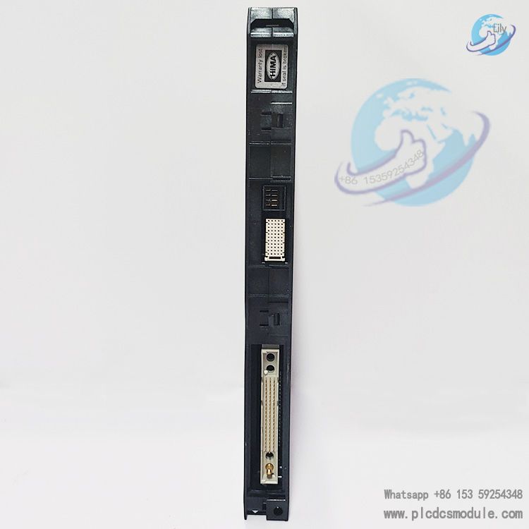
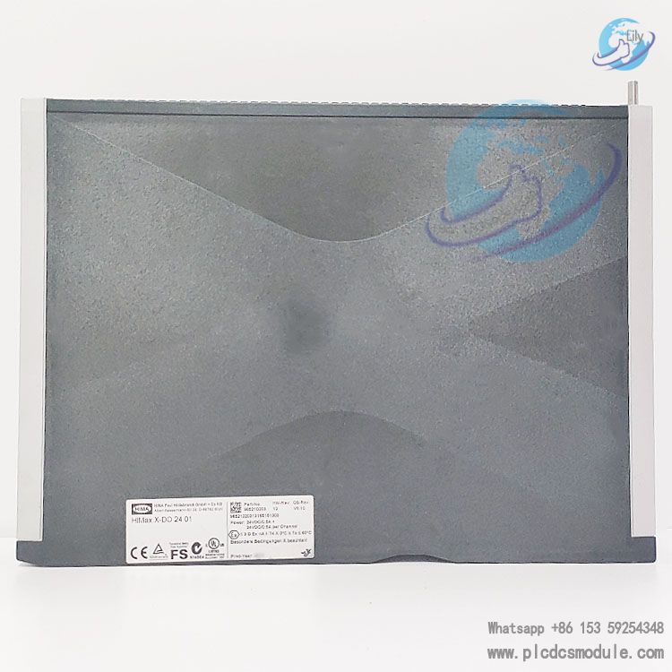
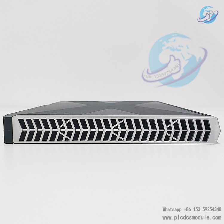
The HIMax X-DO2401 is a digital output module launched by HIMA, exclusively designed for the HIMax Programmable Electronic System (PES). Primarily intended for the construction of safety-related controller systems, it features high safety, high reliability and flexible configurability, and is TÜV certified. This module meets the safety level requirements of SIL 3 (in accordance with IEC 61508, IEC 61511 and IEC 62061), Cat. 4 (in accordance with EN 954-1) and PL e (in accordance with EN ISO 13849-1), making it widely applicable to industrial automation scenarios with stringent safety performance requirements.
Equipped with 24 digital output channels, each channel supports a maximum rated current of 0.5A, and the module has a maximum total continuous load current of 12A under 24VDC operating conditions. Its output voltage equals the supply voltage minus the internal voltage drop, enabling compatibility with resistive, inductive, capacitive loads and lighting fixtures. The module is integrated with line monitoring (SC/short circuit, OC/open circuit), overload protection and other functions, and the system availability can be further enhanced through redundant design. Meanwhile, it must be used with dedicated adapter plates, system cables and other accessories to achieve complete on-site connection and signal transmission.
Download

Core Technical Parameters
1. General Parameters
Supply voltage: 24VDC, with an allowable fluctuation range of -15%~+20%, compliant with PELV (Protective Extra-Low Voltage) and SELV (Safety Extra-Low Voltage) standards; peak ripple (rP) ≤5%.Current draw: Minimum 0.5A in idle state.
Environmental adaptability:
- Operating temperature: 0~+60°C; Storage temperature: -40~+85°C.
- Relative humidity: Max. 95% (non-condensing).
- Protection class: IP20 (compliant with EN 60529:1991 + A1:2000).
- Pollution degree: Class II (in accordance with IEC/EN 61131-2).
- Installation altitude: Below 2000m.Physical specifications: Dimensions (H × W × D) 310×29.2×230mm, approximate weight 1.0kg, no electrical isolation design.
2. Digital Output Parameters
Number of channels: 24 channels, no electrical isolation between channels or from the supply voltage.
Voltage and current characteristics:
- Output voltage: ≥ Supply voltage (L+) minus internal voltage drop; internal voltage drop at high level is 0.8V (at an output current of 0.75A).
- Rated current: 0.5A per channel (range 0.01~0.6A); maximum total allowable current of the module 12A (24VDC).
- Leakage current: Max. 500μA at low level.
Load compatibility:
- Resistive load: Up to the rated current of 0.5A.
- Inductive load: Max. 50H.
- Lamp load (24V lamps): Max. 4W.
- Capacitive load: Max. 100μF.
Protection and response:
- Short-circuit current limitation: Approx. 2A per channel.
- Overcurrent shutdown: Triggered when current >0.75A and duration >50ms.
- Transient overload protection: Max. 43V (rated 33V).
- Switching time: 100μs with resistive load; test pulse (with resistive load) typical value 200μs.
- Overload recovery: The corresponding output channel shuts down in case of overload and attempts to restart after 5 seconds; the process repeats if the overload persists (cyclic restart can be disabled via user program).
3. Line Monitoring (SC/OC) Parameters
Monitoring thresholds: Open circuit (OC) threshold ≤4mA; Short circuit (SC) threshold >0.75A (range 0.75~0.8A).
Monitoring conditions:
- For single-module connection: Load current ≥10mA is required for reliable open-circuit detection, and current >0.8A for reliable short-circuit detection.
- For redundant connection (two modules connected to the same actuator): Load current ≥20mA is required for reliable open-circuit detection, and current >1.6A for reliable short-circuit detection.
Parameter configuration: Supports independent configuration of monitoring function for each channel. The test pulse duration (0~50ms) and monitoring interval (≥40ms) must meet a duty cycle of 0.5% (pulse duration < interval duration). Default monitoring interval is 40ms, and the monitoring function is enabled by default.
Safety Functions and Fault Response
1. Safety Design
Channel Safety Mechanism
Each output channel is connected in series with three safety switches to achieve dual fault tolerance. Each safety switch can be shut down individually via the system bus (I/O bus) or the independent watchdog function.
Safety State
The default safety state is output channel power-off, complying with the "power-off trip" principle. The redundant processor system monitors the expected output values; a reset is triggered if the actual output deviates from the expected value. The module also supports testing of one of the two readback branches.
System Bus Redundancy
Communication with the processor module is realized via a redundant system bus. Redundancy availability is only guaranteed when two system bus modules are both installed and configured in SILworX, which improves the overall reliability of the system.
2. Fault Response
Channel Fault
Only the single faulty output channel is shut down, and the Error LED on the front of the module lights up simultaneously.
Module Fault
All output channels of the module are shut down, and the Error LED lights up.
System Bus Fault
Power-off of all output channels is triggered, and the Error LED lights up.
Diagnostic Prompt
Fault information can be read via the module's LED indicators (e.g., the Field LED flashes to indicate a field fault) and the SILworX software, with support for querying and analyzing fault history records.
Accessories and Connection Schemes
1. Compatible Accessories
Connector Plates
Must be used with the X-CB 009 series connector plates, with different models adapted to various wiring requirements as detailed below:
| Connector Plate Model | Type | Description |
|---|---|---|
| X-CB 009 01 | Non-redundant | Single-channel connector plate with screw terminals |
| X-CB 009 02 | Redundant | Redundant connector plate with screw terminals |
| X-CB 009 03 | Non-redundant | Single-channel connector plate with cable connectors |
| X-CB 009 04 | Redundant | Redundant connector plate with cable connectors |
| X-CB 009 06 | Triple-redundant | Triple-redundant connector plate with screw terminals |
| X-CB 009 07 | Triple-redundant | Triple-redundant connector plate with cable connectors |
System Cables
The X-CA 010 series cables are recommended for connecting connector plates with cable connectors to FTAs. The cable specification is LIYY 48×0.5mm² + 2×2×0.14mm² (stranded fine wire) with an outer diameter of approximately 15.7mm. The bending radius is 5× the outer diameter for fixed installation and 10× the outer diameter for flexible applications. The cable is flame-retardant and self-extinguishing (compliant with IEC 60332-1-2 and IEC 60332-2-2), with standard lengths of 8m, 15m and 30m. It is fitted with coded connectors at both ends and is only compatible with connector plates and FTAs with matching coding.
2. Typical Connection Schemes
Single-channel Wiring for Actuators
Connect the DO channels (DOx+, DOx-) of the module directly to the actuator via a connector plate (e.g., X-CB 009 01). Note: The actuator grounding wires must not be interconnected to avoid the formation of interference coupling loops.
Redundant Wiring for Actuators
Use two X-DO2401 modules and connect the same actuator to the corresponding channels (with identical channel numbers required) of the two modules via a redundant connector plate (e.g., X-CB 009 02) to meet higher availability requirements. Adjust the line monitoring thresholds according to the redundant scenario at the same time.
Wiring for Inductive Loads
Connect a protection circuit such as a freewheeling diode in parallel across the inductive load to prevent damage to the module caused by reverse electromotive force generated when the load is de-energized.
Wiring via FTA
Module → Connector plate with cable connectors (e.g., X-CB 009 03) → X-CA 010 system cable → FTA (e.g., X-FTA 002 01) → Actuator. This scheme is suitable for scenarios requiring centralized management of field wiring. For specific details, refer to the X-FTA 002 01 Manual (HI 801 117 E).
Installation and Configuration
1. Installation Procedure
Pre-installation Preparation
Ensure the working environment complies with the module's environmental requirements. Operators must have ESD (Electrostatic Discharge) protection knowledge, wear an ESD wrist strap, and work in an electrostatic-free area. Prepare matched connector plates and tools such as screwdrivers (e.g., flathead screwdrivers 0.8×4.0mm, 1.2×8.0mm).
Connector Plate Installation
- Place the connector plate with its groove facing upward, insert it into the guide rail of the HIMax baseplate, and align the groove with the guide rail pin.
- Position the connector plate on the cable shielding rail, first tighten the lower fixing screws, then the upper ones (using a 0.8×4.0mm screwdriver).
Module Installation
- Open the fan rack cover (move the latch to the open position, lift the cover and insert it into the fan rack for temporary storage).
- Insert the top of the module into the hook guide rail, rotate the lower part of the module toward the baseplate and press it gently until it clicks into place.
- Tighten the module fixing screws with a 1.2×8.0mm screwdriver, then remove the cover from the fan rack, close the rack and lock the latch.
Module Removal
- Open the fan rack cover first, loosen the module fixing screws, rotate the lower part of the module away from the baseplate, then remove the module from the hook guide rail.
- Close the cover and lock the latch finally. Note: During system operation, the fan rack cover must be open for less than 10 minutes to avoid affecting forced cooling.
Unused Output Handling
Unused output channels may remain open-circuited and require no termination. However, ensure no field-side open wires are present on the unused terminals of the connector plate to prevent short circuits or sparking.
2. SILworX Configuration
The module must be configured in the Hardware Editor of the SILworX programming tool. The core configuration steps and parameters are as follows:
Module-Level Configuration (Module Tab)
- Set the module name, and configure Spare Module (whether a missing module in the redundant group is regarded as a fault, disabled by default) and Noise Blanking (whether the processor module allows noise suppression, enabled by default).
- Status parameters that can be associated with global variables:
- Module OK (BOOL): TRUE when the single module is fault-free or at least one module in the redundant group is fault-free.
- Module Status (DWORD): Bit-encoded module fault information (e.g., 0x00000001 indicates a module fault, 0x00000010 indicates an L1+ voltage fault).
- Timestamp [µs/s]: Output measurement timestamp.
I/O Submodule Configuration (I/O Submodule DO24_01 Tab)
- Basic parameters: Set the submodule name, Output Noise Blanking (whether the module allows output noise suppression, disabled by default), SC/OC Interval (line monitoring interval, 40ms by default), Show Open-Circuit/Short-Circuit (whether to display open/short circuits via the Field LED, enabled by default).
- Diagnostic and control parameters:
- Diagnostic Request/Response (DINT): Used to request/return the diagnostic ID.
- Diagnostic Status (DWORD): Returns the requested diagnostic value.
- Background Test Error (BOOL): Background test fault status.
- Restart on Error (BOOL): Triggers forced restart of the faulty module, FALSE by default.
- Submodule OK (BOOL): TRUE when the submodule and all channels are fault-free.
- Submodule Status (DWORD): Bit-encoded submodule fault information (e.g., 0x00000001 indicates a submodule hardware fault, 0x00000040 indicates module shutdown caused by overcurrent).
Channel-Level Configuration (I/O Submodule DO24_01: Channels Tab)
Independent configuration is available for each channel, including:
- SC/OC Active: Whether to enable line monitoring, enabled by default.
- Max. Test Pulse duration: Test pulse duration (0~50ms, 0ms by default).
- Redund.: Whether to enable channel redundancy (requires redundant module configuration, disabled by default).
Channel status that can be associated with global variables:
- Channel value (BOOL): Channel power-on status.
- Channel OK (BOOL): TRUE when the channel is fault-free and the value is valid.
- OC/SC (BOOL): Channel open-circuit/short-circuit status.
Recommended HIMA Models


 3005319639