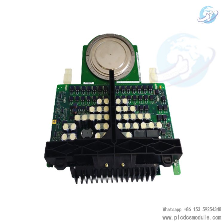
This guide breaks down the core differences between IGCTs and IGBTs across 7 essential dimensions, helping you make informed component selections for your next project.
What Are IGCTs and IGBTs? A Quick Overview
Before diving into comparisons, let’s clarify the basics of each device:
1. Technical Origins & Core Positioning
The foundational roots of IGCTs and IGBTs shape their purpose and target markets.
| Feature | IGCT | IGBT |
|---|---|---|
| Technology Origin | Derived from GTO (Gate Turn-Off Thyristor) | Hybrid of power MOSFET and GTR (Giant Transistor) |
| Launch Era | 1996 | 1980s |
| Core Positioning | Specialized for medium-voltage (6kV/10kV), megawatt-class (MW) systems | Versatile for low-to-medium voltage (380V–3.3kV), small-to-medium power |
| Integration Trait | Gate driver integrated with GCT chip (fiber-optic control) | Gate driver typically external (voltage-signal control) |
2. Device Structure Differences
Structural design defines the fundamental behavior of these components, with the biggest divides in MOS integration and anode design.
IGCT Structure
IGBT Structure
3. Operating Mechanism
How IGCTs and IGBTs turn on/off directly impacts their speed, reliability, and system requirements.
| Operating Phase | IGCT | IGBT |
|---|---|---|
| Turn-On Mechanism | Same as GTO: Positive gate trigger signal prompts cathode carrier emission, forming a high-current A-K path (bipolar conduction). | MOSFET-based: Positive gate voltage (e.g., 15V) creates a MOS channel, triggering bipolar conduction between C-E (carrier injection boosts current). |
| Turn-Off Mechanism | Gate commutation: High negative gate voltage rapidly transfers anode current to the gate, switching instantly to a PNP transistor before turning off—no unstable intermediate state. | MOS channel closure: Gate voltage drops to 0V, eliminating the MOS channel; main current decays gradually (minor tail current requires dv/dt suppression). |
| Snubber Circuit Need | None (no du/dt limitations during turn-off) | Small snubber required in medium-voltage apps (suppresses voltage spikes during turn-off) |
4. Key Performance Parameters Comparison
Performance metrics determine application suitability, with stark differences in loss, capacity, and speed.
| Performance Metric | IGCT | IGBT |
|---|---|---|
| On-State Loss | Extremely low (inherits GTO advantage; e.g., 4.5kV device has ~2.5V forward voltage drop) | Higher (MOS structure creates on-resistance; medium-voltage devices have 3.5V–5V forward voltage drop) |
| Switching Loss | Negligible turn-on loss; low turn-off loss (transparent anode reduces carrier storage) | Moderate (low turn-on loss, but tail current causes significant high-frequency turn-off loss) |
| Switching Speed | Moderate (turn-off time ≈1–2μs), ideal for medium-high frequency (1kHz–10kHz) | Faster (turn-off time ≈0.5–1μs), ideal for high frequency (10kHz–20kHz) |
| Voltage/Current Rating | High single-device capacity (e.g., ABB’s 4.5kV/4kA; 3-level inverter up to 9MVA) | Lower single-device capacity (e.g., Infineon’s 3.3kV/1.2kA; requires series connection for high voltage) |
| di/dt Control | No active control (series reactor required to limit short-circuit current rise) | Active control (adjust switching speed via gate driver to suppress di/dt) |
5. Gate Drive Differences
Drive systems affect integration and reliability, with unique requirements for each device.
IGCT Drive
IGBT Drive
6. Application Scenarios
Their “MV high-power vs. low-MV medium-power” positioning leads to nearly non-overlapping use cases.
| Application Aspect | IGCT Typical Scenarios | IGBT Typical Scenarios |
|---|---|---|
| Voltage Range | Primarily 6kV/10kV medium-voltage systems | Primarily 380V/690V low-voltage to 1.7kV/3.3kV medium-voltage systems |
| Power Range | 0.5MVA–100MVA (large wind turbine converters, rail transit traction converters, grid SVG) | Several kVA–tens of MVA (industrial inverters, renewable energy inverters, household AC inverters) |
| Equipment Types | MW-class inverters, high-voltage motor drives, VSC-HVDC (flexible DC transmission) | Small-to-medium inverters, solar inverters, EV chargers, UPS systems |
7. Pros & Cons
Understanding tradeoffs is critical for optimal component selection.
IGCT Pros & Cons
| Pros | Cons |
|---|---|
| Ultra-low on-state loss for high efficiency | Slower switching speed than IGBTs |
| High single-device capacity (no mass series connection) | No active di/dt control (requires series reactors) |
| No snubber circuit (simplified system design) | Only advantageous in medium-voltage; no low-voltage use case |
| Strong EMI resistance (fiber-optic drive) |
IGBT Pros & Cons
| Pros | Cons |
|---|---|
| Fast switching speed (excellent high-frequency performance) | Higher on-state loss; medium-voltage apps need series connection (reduced reliability) |
| Simple drive (voltage signal) with wide adaptability | Low silicon area utilization; small single-device capacity |
| Active di/dt/dv/dt control (easy protection implementation) | Significant high-frequency switching loss (needs enhanced cooling) |
IGCT vs. IGBT: Which Should You Choose?
The choice hinges on three critical factors:
In short:IGCT is the “efficiency king for MV high power”—optimized for low loss, large capacity, and integrated drives in 6kV/10kV MW systems.IGBT is the “versatile expert for low-MV high frequency”—ideal for fast switching, easy driving, and wide adaptability across small-to-medium power applications.
Final Thoughts
IGCTs and IGBTs are not competitors but complementary solutions in the power electronics ecosystem. As renewable energy, rail transit, and smart grid technologies advance, the demand for both devices will grow—each fulfilling its unique role in enabling efficient, reliable high-power systems.For personalized guidance on component selection, contact our engineering team today.


 3005319639