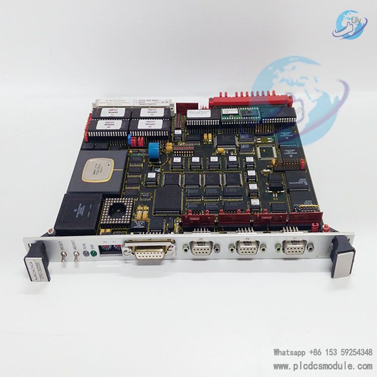
Note; All products on this site are special products, the market price has been fluctuating, the specific customer service offer shall prevail, because the product is a new product, the picture is not a real shot, please confirm with customer service before placing an order model and product, price and other details, the site used, new are for sale, please contact customer service communication. The D136-001-007 motion controller is a product of MOOG, which is widely used in industries such as injection molding, aerospace, steel, wind power, gas and steam turbines. It is more commonly applied in steel mills in northern regions; for example, Wuhan Iron and Steel Company uses it in these fields. In terms of industrial machinery, it is suitable for metal forming machinery, plastic machinery, and metallurgical machinery. In the metallurgical industry, various types of mechanical equipment are used in processes such as smelting, ingot casting, rolling, handling, and packaging, and these devices are also referred to as metallurgical equipment. In the energy sector, it can be used in scenarios such as gas and steam turbines, and wind power generation. Theoretically, the 007 model can replace the 008 model, but this mainly depends on the on-site process and the on-site technical capabilities. This controller is mainly used to directly control actuating valves and servo valves, and is mainly applied to the serial port, mostly for local equipment, that is, equipment located around the control cabinet.
DATA SHEET
 Moog-Controllers.pdf
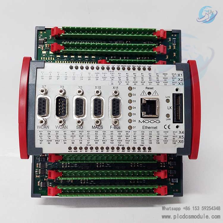
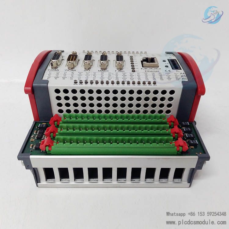
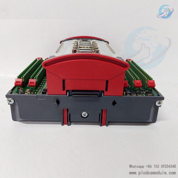
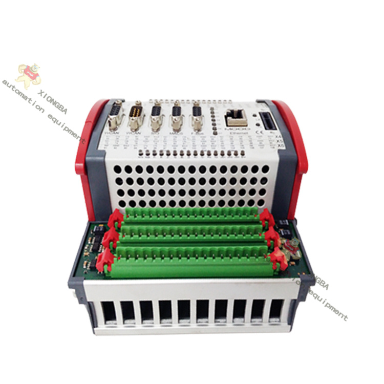
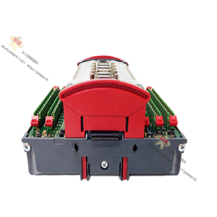
D-71034 Boblingen Made in Germany S/N D3022 The MOOG servo controller D136-001-007 is a high-performance servo controller of the MSC I series with PLC functionality and high-resolution analogue inputs/outputs and position sensor interfaces. Its special design enables fast closed-loop control of two hydraulic servo-actuators.
MOOG servo controllers are available in the MSC I, MSC II, MSC-R and MSD series.
MSC I series models are: D136-001-007, D136-001-008
MSC II models: D136-002-002, D136-002-003, D136-002-004, D136-002-005
MSC-R models: D136-003-002, D136-003-001, D136-004-004, D136-003-005
This article is from the official website of Xiamen Xiongba, please include the following link for reproduction:www.plcdcsmodule.com
Technical Parameters
Processor
- Type: 32-bit PowerPC processor with RISC architecture and a floating-point unit.
- Flash EEPROM: 4 MB, with a typical data retention period of 10 years.
Dimensions and Installation
- Dimensions (W × D × H): 160 x 170 x 85.5 mm (6.30 x 6.69 x 3.36 in).
- Installation dimensions: Width of 149/154.5 mm (5.87/6.08 in).
Environmental Conditions
- Operating temperature range: +5 to +55°C (+41 to +131°F).
- Storage temperature range: -25 to +70°C (-13 to 158°F).
- Maximum average temperature for 24-hour operation: +50°C (+122°F).
- Relative air humidity: 10% to 95% (non-condensing).
- Maximum operating altitude: 2,000 m (6,500 ft); maximum storage and transportation altitude: 3,000 m (9,800 ft).
Power Supply
- Supply voltage for module electronics: 24 V DC (18 to 36 V), compliant with SELV standard of EN 60950-1.
- Current consumption: 0.5 A at no load, 2 A at full load.
- Potential isolation: Module electronics, 24V power supply, digital inputs/outputs, Ethernet, etc., have independent potentials.
Interface Information
Integrated Interfaces
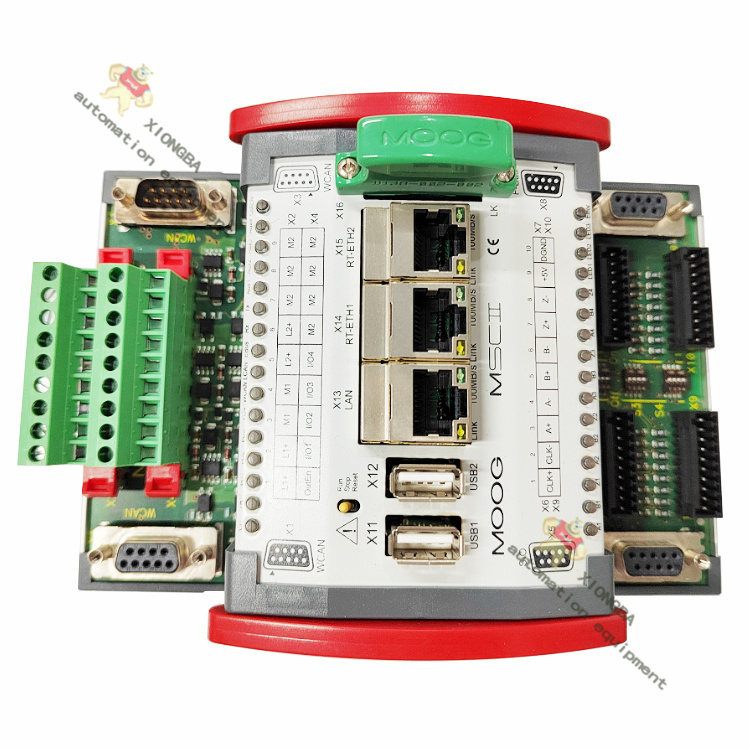
- Ethernet: 1 port, 10 MBit/s, with 8-pin RJ45 connector (10Base-T).
- CAN: 2 independent interfaces, transmission rate adjustable from 10 kBit/s to 1 MBit/s, including WideCAN (2 D-Sub connectors on the front, 1:1 internal connection) and LocalCAN (communicates with other motion controllers via the side Q connector or connects other devices via QEBUS module).
- PROFIBUS-DP slave: 1 port, transmission rate 12 MBit/s.
- Position sensors: 2.
- Serial ports: 2 EIA-232 ports; "MACS" port for communication with MACS software on PC, "SIO" port freely usable in applications.
- Expansion bus (E-Bus): Q connectors on both sides of the module, supporting up to 7 additional modules, including serial bus (5 to 10 MBit/s) and LocalCAN bus.
Digital Inputs/Outputs
- Type: Type 1 (current-consuming type) compliant with IEC 61131-2.
- Quantity: 8, each configurable as input or output in MACS software.
- Supply voltage: 24 V DC (18 to 36 V), compliant with SELV standard of EN 60950-1.
- Maximum current consumption per output: 0.5 A.
- Protection: Equipped with continuous short-circuit protection, thermal overload protection, and overvoltage protection up to ±36 V.
Analog Inputs/Outputs
- Analog inputs: 8, each configurable in MACS software as ±10 V, ±10 mA, or 4 to 20 mA, 16-bit resolution, overvoltage protection up to ±36 V.
- Analog outputs: 2, voltage output ±10 V; each can be additionally configured in MACS software as ±10 mA, ±50 mA, or 4 to 20 mA, 16-bit resolution, with short-circuit protection and overvoltage protection up to ±36 V.
- Reference voltage output: +10 V DC, maximum current 5 mA, with short-circuit protection and overvoltage protection up to ±36 V.
Sensor Interfaces
- Quantity: 2, signal type compliant with EIA-422, with line fault monitoring (input).
- Configuration: Each sensor can be configured as incremental encoder or SSI.
- Incremental encoder interface: Maximum pulse frequency 8 MHz, supporting 4-edge evaluation.
- SSI interface: Supports Gray or binary format, 8 to 32 bits, transmission frequency 78 kHz to 5 MHz.
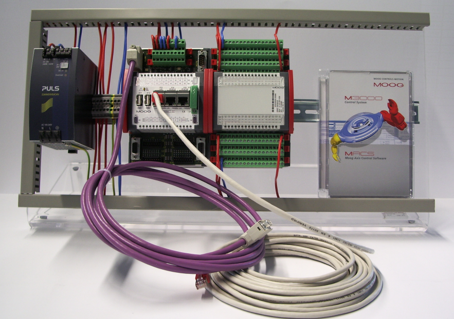
MOOG D136-001-007 belongs to the MSC I series of motion controllers. Its installation and commissioning procedures involve multiple steps, which must be operated in strict accordance with the specifications.
- Check equipment integrity: Inspect whether the controller has any appearance damage, whether all interfaces are intact, and whether the accessories are complete. At the same time, confirm whether there are relevant materials such as product qualification certificates and user manuals.
- Confirm the installation environment: Select an installation environment that meets the requirements of operating temperature (+5 to +55°C), humidity (10% to 95% without condensation), and is free from strong electromagnetic interference. The installation location should be convenient for operation and maintenance, and ensure good heat dissipation of the controller. According to the controller's protection level IP20, it must be installed in an electronic cabinet to avoid direct exposure to harsh environments.
- Fixing the controller: Use the DIN rail installation method to install the controller on an NS 35/7.5 rail that meets the EN 50022 standard. Ensure the installation is firm to avoid loosening affecting normal operation. Pay attention to the direction and position of the controller during installation to facilitate subsequent wiring operations.
- Power wiring: Confirm that the power supply voltage is 24V DC (18 to 36V). Connect the power cord according to the instruction manual, pay attention to the correct connection of positive and negative poles, and ensure stable power supply. At the same time, ensure the potential isolation of the power supply, that is, the potentials of module electronics, 24V power supply, digital input/output, Ethernet, etc., are independent of each other.
- Signal wiring: Connect various signal interfaces, including Ethernet, CAN, PROFIBUS-DP, digital input/output, analog input/output, sensor interfaces, etc. For example, the CAN interface has two independent interfaces (WideCAN and LocalCAN), which need to be connected as required; the analog input can be configured as ±10V, ±10mA, or 4 to 20mA, and connected and set according to actual needs. During the wiring process, ensure good contact to avoid unstable signal transmission caused by virtual connections.
- Familiar with the operation software: Master the basic operation of Moog Axis Control Software (MACS). This software is based on CODESYS and provides a development environment that meets the IEC 61131 standard. Understand the software's functional modules such as programming, testing, debugging, and visualization to facilitate subsequent parameter setting and monitoring.
- Check the correctness of wiring: Check all wiring again for correctness, and verify them one by one against the wiring diagram. Especially the polarity and connection position of power wiring and signal wiring. Proceed to the next step only after confirming that there are no errors to prevent damage to the equipment due to incorrect wiring.
- Parameter setting: Open the MACS software and set the controller parameters according to actual application requirements. Such as setting the control mode, PID parameters (if needed), number of axes, communication parameters, etc. For example, if it is used to control the movement of two axes, the relevant parameters of the axes must be set correctly; in terms of communication parameters, set the communication rate and node address of interfaces such as Ethernet and CAN.
- Input and output testing: Use MACS software or other testing tools to test the functions of digital input/output and analog input/output. Input different signals to the analog input port to check whether the controller can collect and process them correctly; control the digital output port to see if the corresponding equipment acts as expected.
- Communication testing: Test the communication functions of interfaces such as Ethernet, CAN, and PROFIBUS-DP. Connect other devices (such as upper computers, sensors, etc.) to check whether data transmission is normal and whether there are packet loss, errors, etc.
- Motor control testing: Connect the servo motor, enable the controller, and perform motor jog testing, speed testing, position testing, etc. Observe the operating status of the motor, such as whether the speed is stable and whether the position control is accurate, to judge the controller's control effect on the motor. If the motor runs abnormally (such as jitter, excessive noise, failure to start normally, etc.), check whether there are problems with parameter settings, wiring, and the motor itself.
Customers who purchased this product are also browsing the following products:
MOOG D136-001-001 Module Servo Controller
MOOG D138-002-001 Passcode Dog
GE Hydran 201Ti Mark IV Essential DGA monitoring for transformers
HONEYWELL LG1093AC01 Flame Detector


 3005319639