


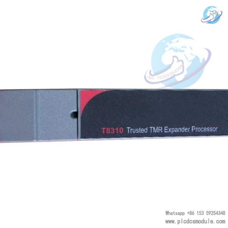
Building on the core architecture of the base T8310 model, the T8310C adds professional conformal coating to withstand harsh industrial conditions including corrosion, humidity, and dust. It retains key features such as the HIFT TMR hardware fault-tolerant architecture, rapid fault diagnostics, and hot standby redundancy, effectively isolating faults and maximizing system availability. It serves as a critical control component in high-risk industrial sectors such as petrochemical, oil & gas, power generation, and rail transit.(Physical pictures and actual prices are available upon contacting customer service.)
Download

| Item | Specification |
|---|---|
| Backplane (IMB) Power | 20 Vdc ~ 32 Vdc |
| Field Power | N/A |
| Power Consumption | 45 W (backplane-powered) |
| Mounting Location | T8300 Expansion Chassis processor slots |
| Electrical Isolation | 50 V basic insulation between module and backplane power |
| Fuse | Non-user-serviceable |
| Max. Expansion Communication Distance | TC-301 copper: 30 m; T8314 fiber: 10 km |
| Operating Temperature | 0 °C ~ +60 °C (32 °F ~ 140 °F) |
| Storage Temperature | -25 °C ~ +70 °C (-13 °F ~ 158 °F) |
| Relative Humidity | 10% ~ 95%, non-condensing |
| Dimensions (H × W × D) | 266 mm × 31 mm × 303 mm (10.5 in × 1.2 in × 12.0 in) |
| Weight | 1.33 kg (2.9 lb) |
| Environmental Standards | Refer to document 552517 |
Core Architecture and Fault-Tolerant Design
TMR+FCR Dual-Layer Fault-Tolerant Structure
The module is designed based on a Triple Modular Redundant (TMR) lockstep configuration, with three primary Fault Containment Regions (FCR A/B/C) and one non-critical monitoring and display Fault Containment Region (FCR D).Each primary FCR is independently equipped with an Expander Bus, IMB interface, control logic, communication transceiver, and power supply. FCR D is responsible for front panel indication and monitoring, and is included in the cross-FCR Byzantine voting mechanism. Electrical isolation is implemented between FCRs to completely prevent fault propagation across regions.
Hardware-Implemented Fault Tolerance (HIFT)
Fault-tolerant logic is implemented using a purely hardware architecture, combined with dedicated hardware and software testing mechanisms. Compared with software-based fault tolerance, fault detection and response speed is significantly improved.The module supports a 3-2-0 fault-tolerant operating mode: the system remains fully operational under single-channel faults, meeting SIL 3 safety requirements.
Full-Link Voting Mechanism
All messages and control signals on the Expander Bus and IMB bus are resynchronized and subjected to majority voting (Byzantine voting). Transmission errors are automatically corrected and masked, while signal fault discrepancies are detected and reported to avoid potential latent failures.
Coating Protection Features
The T8310C features industrial-grade anti-corrosion and dust-proof conformal coating, covering the module PCB and core electronic components. Its key protective benefits include:
- Resistance to corrosive gases (e.g., acid and alkaline gases in chemical plants, hydrocarbon gases in oil and gas fields), moisture condensation, and dust contamination, reducing component oxidation and short-circuit risks.
- Improved long-term operational stability and extended service life in high-humidity (10%–95% non-condensing) and dusty industrial environments.
- No impact on heat dissipation or electrical connections, with full compatibility with the original module’s installation, removal, and maintenance procedures.
Key Functions and Performance
1. Bus Interconnection and Expansion
As the core bridging component between the Expander Bus and IMB bus:
- The Expander Bus uses a triple redundant point-to-point architecture, delivering 1.5 Gbps high-speed data transmission via unshielded twisted-pair (UTP) cable. It supports TC-301 copper cable (max. 30 m) and T8314 fiber-optic transceiver unit (max. 10 km), enabling local and remote multi-chassis expansion.
- The IMB bus is fully compatible with the controller chassis, with a transmission rate of 12.5 Mbps. It supports 8-bit bi-directional data transfer, bus clocking, system watchdog, and power failure warning signals in triple redundant form, ensuring highly reliable communication between I/O modules in the expansion chassis and the TMR processor.
2. Power and Clock Management
- Dual redundant 24 Vdc power (20–32 Vdc) is obtained from the expansion chassis backplane. Each FCR has independent power input; a single power fault does not affect other channels. The 24 Vdc level is monitored in real time and reported to the TMR processor, with voltage values quantized in units of 1/512 V, supporting arithmetic scaling and engineering unit conversion.
- The active module provides a synchronized IMB clock signal of 12.5 M symbols per second, with independent clocking for odd/even module positions and backup expansion processors to minimize clock loading and ensure bus synchronization.
3. Message and Control Signal Forwarding
- Enables cross-chassis expansion of the IMB bus. The active module forwards messages received from the Expander Bus to the IMB bus in the expansion chassis, and returns response messages from the IMB bus to the Expander Bus. Only locally addressed messages are processed; all others are passed through transparently.
- Performs triple redundant forwarding and voting for three core control signals: power failure warning, system watchdog, and command response control, ensuring signal synchronization in the expansion chassis even if the controller chassis fails.
4. Hot Standby and Redundancy Switching
- Supports hot-standby and module backup configuration with a dual-slot partner arrangement (PL1/PL2). The primary module is installed in the left slot by default and operates in active mode, while the backup module remains in standby. Automatic or manual switchover occurs upon failure.
- Supports hot replacement: faulty modules can be replaced without shutting down the system. The new module initializes automatically upon power-up, and the TMR processor can trigger automatic failover without disrupting core system operation.
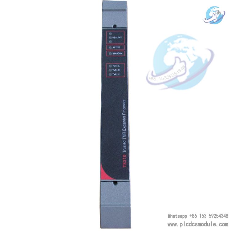
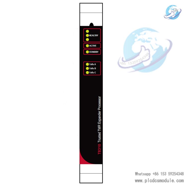
Front Panel and Status Indication
The module is equipped with a user-friendly front panel, with all statuses clearly indicated by LEDs. Conformal coating does not affect the operation of the LEDs or mechanical components:
- Healthy LED: Solid green = no fault; flashing red = corresponding channel (A/B/C) fault.
- Operating Mode LEDs: Active (green) = operating mode; Standby (solid green) = standby mode with no transmission activity.
- Communications Activity (TxRxA/B/C): Off = no activity/fault; green = receive activity; red = transmit activity.The panel includes module latches and ejector tabs, used with a dedicated release tool for easy insertion, removal, and failover operations.
Installation and Configuration
- Installation Requirements: The module may only be installed in the left two processor slots (PL1/PL2) of the T8300 Expansion Chassis; installation in other slots is not permitted. The two processor slots must be interconnected via a cable shroud assembly. Before installation, verify correct chassis addressing and ensure no bent pins or physical damage to the module connector.
- Polarization Keying: The module is factory-keyed. The mating cable requires removal of keying pins 1, 2, and 5 to prevent incorrect insertion. Both keying strips must be polarized for partner-slot installation.
- No Local Configuration Required: The module requires no local configuration. Status information can be read and configured via the IEC 61131 toolset. The chassis (2–15) and slot (13/14) numbers must be specified in the I/O connection table; the system INI configuration file automatically recognizes the module in the expansion chassis.
Fault Diagnosis and Maintenance
Multi-Dimensional Fault Reporting
Faults are reported via three channels: front panel LEDs, application status variables, and external system communication interfaces.The system distinguishes between:
- External wiring faults: resolved by on-site repair.
- Internal module faults: resolved by module replacement.
Rapid Fault Localization
A detailed fault symptom–cause–solution table is provided for quick troubleshooting of typical conditions: all LEDs off, single/multiple FCR red flashing, communications LEDs off, incrementing error counters, etc.Possible causes include power failure, FCR fault, bus cable fault, and EMI interference.
Standard Maintenance Procedures
- Only qualified industrial electronics maintenance personnel are permitted to service the module.
- Static discharge precautions must be observed at all times; do not touch exposed connector pins or remove the module housing.
- In explosive atmospheres, do not insert or remove the module under power. Ensure the area is free of flammable materials.


 3005319639