


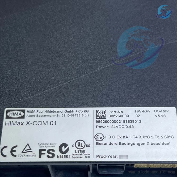
HIMA HiMax X-COM 01 (Part No.: 985260000) is a standard communication module developed by Germany-based HIMA exclusively for the HiMax Programmable Electronic Safety System (PES). It is not equipped with fieldbus sub-modules and needs to be used together with the X-CB 001 02 adapter board to form a complete communication unit, serving as the core hardware for Ethernet and fieldbus data exchange within the HiMax system.
This module does not execute safety control logic. It is dedicated to data forwarding for safety-related protocols and standard industrial protocols. Designed for SELV/PELV extra-low voltage power supply environments, it is widely applied in industrial safety automation. Featuring high stability, strong anti-interference capability and easy deployment and maintenance, it is compatible with SILworX V5 configuration software and acts as a basic model for communication networking of the HiMax system.
DOCUMENT DOWNLOAD
![]() HIMA HiMax X-COM 01 985260000 Communication Module.pdf
HIMA HiMax X-COM 01 985260000 Communication Module.pdf
Detailed Specifications
1. Basic Hardware Parameters
| Parameter | Technical Specification |
|---|---|
| Supply Voltage | 24 VDC (tolerance: -15% ~ +20%), compliant with SELV/PELV standards |
| Operating Current | Min. 0.25 A, Max. 0.46 A |
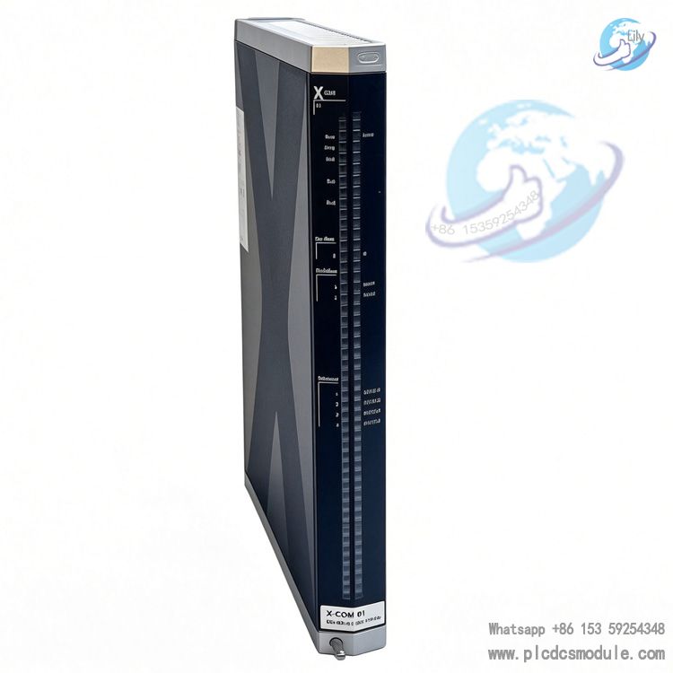
| Physical Dimensions | 310 mm × 29.2 mm × 230 mm (Height × Width × Depth) |
| Weight | Approx. 1.3 kg |
| Ingress Protection | IP20 |
| Operating Environment | Temperature: 0 ~ 60 °C; Relative Humidity: ≤95% (non-condensing); Pollution Degree II; Altitude: < 2000 m |
| Storage Environment | Temperature: -40 ~ 85 °C |
2. Interface Specifications
Ethernet Interface (4 × RJ45 Ports)
Supports 10BASE-T/100BASE-TX with auto-negotiation for full/half duplex and auto crossover function. IP address, subnet mask and gateway are fully configurable. It supports VLAN, LLDP, port mirroring and other network functions. Speed, flow control and broadcast storm suppression can be set individually for each port.
Fieldbus Interface (2 × 9-pin D-Sub, optional)
The standard X-COM 01 has no built-in sub-modules. Protocols can be enabled by installing original sub-modules, including RS485 (Modbus Master/Slave), PROFIBUS DP Master/Slave, RS232/RS422 and SSI. The maximum baud rate of FB1 for PROFIBUS is 12 Mbit/s, and 1.5 Mbit/s for FB2. Only one protocol is allowed per single interface.
System Bus
Dual redundant system buses realize data communication with HiMax processor modules and ensure fault tolerance of communication links.
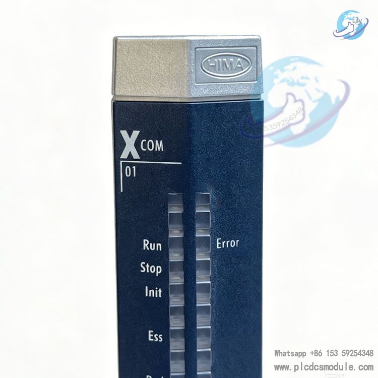
3. Status Indication System
Multiple LED indicators are arranged on the front panel. A full lamp self-test is performed automatically after power-on. Four groups of indicators with fixed flashing frequencies are adopted for status identification.
- Module Status LEDs (Run/Error/Stop/Init): Green Run LED indicates normal operation; red Error LED alerts hardware or voltage faults; yellow Stop/Init LED indicates stop status, initialization and configuration errors.
- Redundancy LEDs (Ess/Red): Indicate fieldbus redundancy operation, synchronization errors and missing redundant partners.
- System Bus LEDs (Sys Bus A/B): Show physical and logical connection status of the buses.
- Fieldbus & Ethernet LEDs: Yellow LEDs display normal bus operation; red Fault LEDs trigger alarms for bus failures. Ethernet LEDs flash along with data transmission, and can identify IP address conflict, duplex mode abnormality and data collision.
4. Software & Functional Features
Configuration Software
Compatible with SILworX V4 and V5. Network parameters including IP address, routing, ARP aging time, MAC address learning rules and ICMP mode are configurable, with a maximum of 8 routing entries supported.
Port Classification
Dedicated UDP/TCP communication ports are defined for different services, such as SNTP time synchronization, Modbus, SafeEthernet, PROFINET and SILworX programming & debugging.
Fault Handling
The module enters ERROR STOP mode immediately once a fault is detected during self-test, cutting off data exchange with external devices and local process modules, and then restarts automatically to prevent fault propagation.
Storage & Diagnostics
Non-volatile memory stores the operating system and fault logs. Historical diagnostic data can be retrieved via SILworX.
Periodic Testing
A Proof Test for integrity verification is required every 10 years in accordance with relevant standards to guarantee long-term operational reliability.
5. Accessories & Model Coding Rules
This module must be used together with the separately purchased X-CB 001 02 adapter board. When fieldbus sub-modules are installed, the model will be updated to X-COM 010 XY (X = Protocol code of FB1, Y = Protocol code of FB2). Fieldbus sub-modules can only be installed by the original manufacturer. Unauthorized disassembly and modification by users are prohibited.
Core Advantages
Reliable Architecture with Redundancy Protection
It adopts redundant system buses. Dual system buses (A/B) operate independently, so a failure of one bus will not disrupt overall communication. The built-in self-test function of the processor system triggers an automatic ERROR STOP and restart upon faults, blocking abnormal data transmission and avoiding cascading system risks.
High Integration & Flexible Expandability
Equipped with 4 Ethernet ports and 2 expandable fieldbus interfaces. The Ethernet ports support auto-negotiation and auto-crossover. Users can install original sub-modules to switch fieldbus protocols as needed. A single module fulfills networking requirements for various devices.
Excellent Adaptability to Industrial Environments
Operating temperature: 0~60°C; storage temperature: -40~85°C. With IP20 protection rating, it suits Pollution Degree II and working altitude below 2000 m. It can also be applied in regular hazardous areas with additional protective measures, adapting to harsh industrial conditions.
Easy Maintenance & Hot-Swap Support
The module supports hot swapping during system operation. The adapter board can remain on the base without rewiring. Grouped LED indicators display full operating status for visual fault diagnosis. Diagnostic logs can be retrieved remotely via SILworX, greatly simplifying maintenance work.
Wide Protocol Compatibility & Superior Safety
It natively supports SafeEthernet, and is compatible with mainstream industrial protocols including Modbus, PROFIBUS DP, SSI, RS232/RS422/RS485. It separates safety and general data transmission, fully complying with communication specifications for Safety Instrumented Systems (SIS).
Comprehensive Compliance
The module conforms to IEC/EN 61131-2 industrial standards and features built-in ESD protection. Complete electrostatic protection regulations apply to module installation, removal and maintenance. Traceable hardware and firmware versions meet the audit requirements for industrial safety equipment.
Application Scenarios
Positioned for the HiMax safety system, this module is dedicated to industrial safety automation. Its main application scenarios are as follows:
Safety Instrumented Systems (SIS)
Deployed in Emergency Shutdown (ESD) and Fire & Gas (F&G) systems for high-risk industries such as petroleum, chemical, natural gas and coal chemical sectors. It enables secure data exchange between safety controllers and third-party DCS, PLC and remote I/O units.
Boiler & Turbine Safety Control Systems
Used for boiler safety monitoring and turbine trip protection systems in the power industry. It connects with host computers and local I/O modules via Ethernet and fieldbus to transmit safety interlock data.
Rail Transit & Port Safety Equipment
Applied to port cranes and rail transit signal safety systems for networking and communication between safety control units, delivering reliable performance under complex industrial electromagnetic environments.
Compliant Automation for Pharmaceutical & Food Industries
Serves for production line interlock systems complying with industrial safety regulations to transmit process safety parameters. Featuring IP20 protection and wide temperature tolerance, it adapts to operating conditions in clean workshops.
Redundant Networking for General Industry
Acts as a communication hub of the HiMax system in standard factory automation to build redundant communication networks and ensure uninterrupted data transmission for critical equipment.
FAQ
Q: Does X-COM 01 (985260000) come with the X-CB 001 02 adapter board? Can it be used standalone?A: The adapter board is not included and must be purchased separately. This module requires X-CB 001 02 for normal wiring and operation. The two components are functionally matched and indispensable.
Q: Can I install sub-modules on-site to add PROFIBUS interface to X-COM 01 afterwards?A: No. Fieldbus sub-modules can only be assembled or modified by HIMA original manufacturer. Unauthorized disassembly will damage the module and void the warranty. Please contact your supplier to send the unit back to factory for upgrade to X-COM 010 series.
Q: How to tell X-COM 01 apart from its variants equipped with bus sub-modules during procurement?A: Distinguish by part number and model designation. Part No. 985260000 refers to standard X-COM 01 without sub-modules. Models with fieldbus have different part numbers and are named X-COM 010 XY. Please specify protocol codes X and Y when placing orders.
Q: Is this module applicable in hazardous areas? Are extra accessories required?A: The module itself has no explosion-proof certification, yet it can be used in Ex hazardous areas with additional on-site explosion-proof measures. No extra explosion-proof parts for the module are needed; just comply with local explosion-proof regulations.
Q: The red Error LED stays on. What are the causes and troubleshooting steps?A: Steady or flashing Error LED indicates a fault detected by self-test. Common causes include abnormal supply voltage, hardware damage and OS loading failure.Troubleshooting: 1. Verify the 24 VDC power supply is within the permitted tolerance range; 2. Power off, then remove and reinsert the module; 3. Retrieve diagnostic logs via SILworX for fault location. Replace the module directly if hardware failure is confirmed.
Q: Ethernet connection is normal, but SILworX fails to access the module. How to fix it?A: This is mostly caused by incorrect IP, ARP or routing settings.
- Ensure the IP address, subnet mask and gateway are on the same network segment as the host PC;
- Extend the ARP aging time for cross-routing scenarios;
- Confirm IP forwarding is disabled (mandatory);
- Reboot the module to reset network status.
Q: Can X-COM 01 be hot-swapped during system operation? What precautions should be taken?A: Hot swap is supported, allowing module replacement without system shutdown.Notes: 1. Wear an anti-static wristband throughout the operation for ESD protection; 2. Do not leave the fan cover open for more than 10 minutes to avoid heat dissipation issues; 3. Avoid prying forcibly to prevent damage to base connectors.
Q: What regular maintenance is required for long-running modules? What is the test cycle?A: Routine maintenance: Upgrade the operating system via SILworX during system downtime and clean dust off wiring terminals.Compliance test: Perform a Proof Test every 10 years in accordance with relevant standards, following the instructions in HIMA Safety Manual HI 801 003 E.On-site repair is prohibited for faulty modules. Replace it with an identical spare part and send the defective unit back to the factory for maintenance.


 3005319639