What is a PLC?
A PLC, or "Programmable Logic Controller," is a computer specifically designed to operate reliably in harsh industrial environments (such as extreme temperatures, humidity, dryness, and dusty conditions). It is primarily used to automate industrial processes, including scenarios like factory assembly lines, ore processing plants, and sewage treatment facilities.
PLCs share several similarities with household personal computers, as both have a power supply, central processing unit (CPU), input/output (I/O) interfaces, memory, and an operating system (though the operating systems differ). However, their key distinction lies in the PLC's ability to perform discrete and continuous control functions that personal computers cannot—such as real-time coordinated control of hundreds of valves and motors on a production line, or continuous regulation of parameters like temperature and pressure. Additionally, PLCs are more resilient in harsh industrial environments. In essence, a PLC is a "ruggedized" digital computer dedicated to managing electromechanical processes in industrial settings.
In the field of automation, PLCs play a crucial role and are core components of large-scale SCADA (Supervisory Control and Data Acquisition) systems. They can be programmed according to the specific operational requirements of a process flow. In manufacturing, as production needs change (e.g., switching product models or adjusting production rhythms), control systems often require reprogramming. To address this, PLC-based control systems were developed. Below, we first introduce the basics of PLCs before exploring their various applications.
PLC Basics
PLCs wer
How PLCs Work
The working principle of a PLC can be understood through a cyclic scanning method called the scan cycle. This cycle is analogous to a human's "observe-think-act" process, repeating continuously to achieve real-time control.
The PLC scanning process includes the following steps:
Initialization and Timing: The operating system starts cyclic operation and monitors scan time (ensuring a stable scan cycle to avoid control delays due to program complexity).
Read Inputs: The central processing unit (CPU) reads data from input modules and checks the status of all inputs (e.g., whether a sensor is triggered or a button is pressed). These states are stored in the input image area of memory.
Execute Programs: The CPU executes user or application programs written in PLC programming languages such as Ladder Diagram (LD), Structured Text (ST), and Function Block Diagram (FBD). During execution, the CPU performs logical operations, judgments, and calculations based on data in the input image area.
Diagnostics and Communication: Next, the CPU performs all internal diagnostics (checking for hardware malfunctions, memory errors, etc.) and communication tasks (exchanging data with HMI interfaces, other PLCs, or host computers).
Update Outputs: Based on program execution results, the CPU writes data to the output image area of the output module, which then transmits signals to external devices (e.g., starting a motor or opening a valve) to update all output states.
Cycle Operation: As long as the PLC is in run mode, this process continues. The scan cycle typically ranges from a few milliseconds to tens of milliseconds, ensuring real-time responsiveness to industrial processes.
e invented by Dick Morley in 1964, initially to replace traditional relay control circuits and solve wiring challenges in automobile manufacturing when production lines were reconfigured. Since then, PLCs have revolutionized industrial and manufacturing sectors with their flexibility and reliability. Modern PLCs offer a wide range of functions, including precise timing (achieving millisecond or even microsecond-level control), high-speed counting (for counting products, monitoring motor speeds, etc.), complex calculations (such as proportional-integral-derivative operations in PID algorithms), logical comparisons (judging whether parameters meet preset conditions), and processing of various analog signals (such as continuous changes in temperature, pressure, and flow).
Compared to "hard-wired" control systems, the main advantages of PLCs lie in their programmability and flexibility: after programming, modifications incur minimal costs (only the programmer's time); in contrast, modifying a hard-wired control system typically requires rewiring from scratch, which is more costly and time-consuming. Let’s use an example to better understand this advantage:
Imagine a light connected to a switch—usually, the light has only two states: on or off. Now, suppose the requirement is that the light turns on 30 seconds after the switch is flipped. With a hard-wired setup, we would be stuck; the only solution would be to rewire and add a time relay, a minor change that is surprisingly cumbersome (involving powering off, disconnecting wires, reconnecting, testing, etc.).
A PLC solves this problem without additional wiring or hardware. It only requires modifying the code (e.g., adding a 30-second delay instruction in the program) to program the PLC to turn on the light 30 seconds after the switch is activated. Thus, PLCs can easily integrate multiple inputs and outputs—for example, simultaneously receiving signals from temperature sensors, pressure switches, and photoelectric sensors, then interlock control motors, valves, alarms, and other devices. This is just a simple example; in reality, PLCs can control larger, more complex processes (such as entire automotive welding lines or fully automated chemical reactors) and can be customized to user scenarios and needs.
How PLCs Work
The working principle of a PLC can be understood through a cyclic scanning method called the scan cycle. This cycle is analogous to a human's "observe-think-act" process, repeating continuously to achieve real-time control.
The PLC scanning process includes the following steps:
Initialization and Timing: The operating system starts cyclic operation and monitors scan time (ensuring a stable scan cycle to avoid control delays due to program complexity).
Read Inputs: The central processing unit (CPU) reads data from input modules and checks the status of all inputs (e.g., whether a sensor is triggered or a button is pressed). These states are stored in the input image area of memory.
Execute Programs: The CPU executes user or application programs written in PLC programming languages such as Ladder Diagram (LD), Structured Text (ST), and Function Block Diagram (FBD). During execution, the CPU performs logical operations, judgments, and calculations based on data in the input image area.
Diagnostics and Communication: Next, the CPU performs all internal diagnostics (checking for hardware malfunctions, memory errors, etc.) and communication tasks (exchanging data with HMI interfaces, other PLCs, or host computers).
Update Outputs: Based on program execution results, the CPU writes data to the output image area of the output module, which then transmits signals to external devices (e.g., starting a motor or opening a valve) to update all output states.
Cycle Operation: As long as the PLC is in run mode, this process continues. The scan cycle typically ranges from a few milliseconds to tens of milliseconds, ensuring real-time responsiveness to industrial processes.
Physical Structure of a PLC
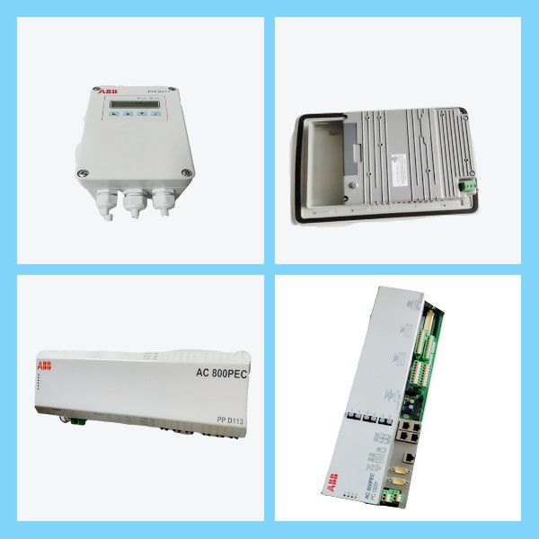
The structure of a PLC is nearly similar to that of a computer but is reinforced for industrial environments.
Programmable Logic Controllers continuously monitor input values from various input sensing devices (such as accelerometers, weight scales, and hard-wired signals) and generate corresponding outputs based on production characteristics and industry requirements. A typical PLC block diagram consists of five parts:
Rack or Chassis
Power Supply Module
Central Processing Unit (CPU)
Input/Output Modules
Communication Interface Module
Rack or Chassis
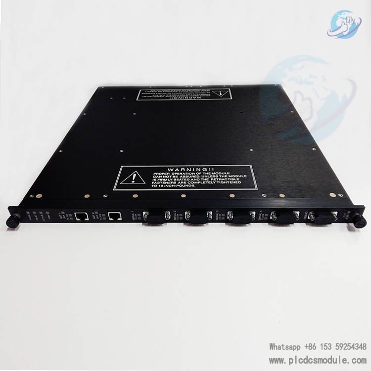
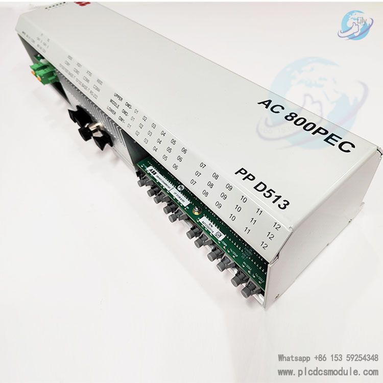
In all PLC systems, the PLC rack or chassis is the most important module and the physical backbone of the system. It provides mechanical support and electrical connections (via an internal bus) for other modules. PLCs come in various shapes and sizes: small PLCs are usually integrated designs without independent racks; for more complex control systems, larger PLC racks (such as 19-inch standard racks) are required. Small PLCs have fixed I/O pin configurations with limited expandability; thus, modular rack-mounted PLCs were developed, featuring a plug-in design that can accommodate different types of I/O modules (e.g., digital I/O, analog I/O, special function modules). All I/O modules are installed inside this rack or chassis and communicate with the CPU via a backplane bus.
Power Supply Module
This module provides stable power required for the entire PLC system. It converts available industrial alternating current (usually 220V AC or 380V AC) into direct current needed for the PLC's internal circuits (typically 24V DC or 5V DC) to supply the CPU and I/O modules. PLCs generally use 24V DC as the standard power supply for external sensors and actuators (facilitating unified wiring and selection). A few PLCs use isolated power supplies (electrically isolating the input power from the output power) to improve anti-interference capabilities and safety, preventing external voltage fluctuations, interference, or faults from affecting the PLC's internal circuits.
Central Processing Unit (CPU) Module and Memory
The CPU module is the "brain" of the PLC, containing a central processing unit, ROM (read-only memory), and RAM (random-access memory):
ROM Memory: Stores fixed programs, including the PLC's operating system (responsible for managing scan cycles, module communication, diagnostics, and other low-level functions), driver programs (supporting identification and control of different I/O modules), and factory-preset basic programs. Data in ROM is not lost when power is turned off.
RAM Memory: Temporarily stores user-written application programs, real-time data (such as input/output states, intermediate variables, current values of timers and counters, etc.). When data in RAM needs to be retained after a power outage, it is usually equipped with a lithium battery or supercapacitor as a backup power source.
The CPU is the core of the PLC, with a high-performance microprocessor (such as a 32-bit or 64-bit processor). Microprocessor-based CPUs have replaced timers, relays, and counters in traditional relay control circuits, implementing logical control through software programs, greatly improving flexibility. PLCs can integrate two types of processor functions: single-bit processors (processing logical operations for digital signals, such as AND, OR, NOT) and word processors (processing multi-bit data, such as integer and floating-point calculations for text processing, numerical analysis, data recording, etc.). The CPU workflow is: reading input data from sensors via input modules, processing it according to user programs, and finally sending instructions to control devices via output modules. The CPU also contains other electronic components (such as bus interfaces and clock circuits) for connecting cables used by other units.
Input/Output (I/O) Modules
Input/output modules (I/O modules) are the "bridge" between PLCs and external devices (sensors, actuators). Have you ever wondered how PLCs sense physical parameters like temperature, pressure, and flow? Of course, PLCs receive these signals through input modules and control actuators through output modules. Input devices can be start/stop buttons, limit switches, photoelectric sensors, temperature transmitters, etc.; output devices can be electric heaters, solenoid valves, AC contactors, indicator lights, alarms, etc. I/O modules help connect input and output devices to the microprocessor and implement signal conversion and isolation.
Working Principle of Input Modules
PLC input modules have four main functions:
Receive External Signals: Input module interfaces receive signals from process equipment (which may be signals of different voltage levels such as 220V AC or 24V DC).
Signal Conversion: Convert external signals into standard signals recognizable by the PLC's internal microprocessor (usually 5V DC digital signals). For example, converting a 220V AC button signal into a 5V DC logic level.
Electrical Isolation: Use isolation components such as optocouplers to isolate the high-voltage circuits of external devices from the low-voltage circuits inside the PLC, preventing external voltage fluctuations, interference, or faults from affecting the PLC's core circuits.
Signal Transmission: Send the converted signals to the CPU's input image area for use during program execution.
Input modules are divided into a power supply section (connected to external devices, handling high-voltage signals) and a logic section (connected to the PLC's internal bus, handling low-voltage signals), which are completely electrically isolated. Taking an AC input module as an example: when an external button is closed, 220V AC power is supplied to a bridge rectifier circuit through a current-limiting resistor, rectified to DC, and stabilized by a Zener diode to provide operating voltage for a light-emitting diode (LED); when the LED lights up, the light irradiates a phototransistor, turning it on, thereby outputting a 5V DC logic high-level signal to the CPU, indicating a valid input.
Working Principle of Output Modules
The working principle of PLC output modules is similar to that of input modules but with the signal flow reversed: they convert low-voltage logic signals output by the CPU into high-voltage signals acceptable to external actuators, connecting output loads and the processor. Therefore, the first part of an output module is the logic section (receiving signals from the CPU), followed by the power supply section (driving external loads).
Taking an AC output module as an example: when the CPU generates a logic high signal, the LED inside the module lights up, and the light irradiates a phototransistor, turning it on; after the transistor is turned on, it sends a trigger pulse to the gate of a triac (an AC switching component), turning the triac on, thereby applying 220V AC power to external loads (such as contactor coils, indicator lights). Isolation blocks are also used to isolate the logic section (low voltage) and control section (high voltage) to ensure safety and anti-interference.
Communication Interface Modules
Communication modules help connect PLCs to other PLCs and computers in remote locations, enabling centralized monitoring, data sharing, and collaborative control, and are important components of the Industrial Internet of Things (IIoT).
Types of PLCs
PLCs can be divided into various types based on structure and function. Common classification methods are as follows:
Classification by Structure: Fixed/Compact PLCs and Modular PLCs
Compact PLCs
Modular PLCs
Classification by Output Type
Classification by Physical Size and Functional Scale
Some PLC manufacturers include:
Applications of PLCs
PLCs have a variety of application scenarios, including:


 3005319639