


The TK-3 is outfitted with two key components: a swash plate and a micrometer shaft. Both components come with 4140 steel as the observation surface, and users can replace it with a surface made of the same material as the actual rotor if necessary.
Note: Bently Nevada's sensors operate on the eddy current principle. Therefore, the material of the TK-3's observation surface must match that of the rotating shaft with which the probe actually works. Only in this way can the calibration accuracy be guaranteed. Steels that exhibit the same response curve as 4140 steel do not require replacement. However, if materials such as copper, aluminum, brass, or titanium serve as the actual working surfaces for the probe, the observation surface of the TK-3 must be replaced. We offer a variety of materials for the observation surface; should you have any needs, please contact your dealer or service representative.
The micrometer shaft is used to check the voltage variation characteristics corresponding to the distance changes between the probe and the preamplifier. It can also be utilized for measuring shaft displacement. The swash plate generates vibration and keyphasor reference signals. Peak-to-peak vibration can be controlled by adjusting the sensor position via the manually operated rocker assembly. The speed control button is used to regulate the rotation speed of the swash plate.
If the probe cannot be removed from the equipment or direct testing is not feasible, a probe of the same model can be used as a substitute to fulfill the testing requirements. The monitoring system can be calibrated by observing the distance change between the measured surface and the probe, or by measuring the output of the monitor.
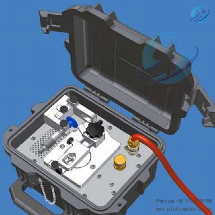
Application Warning: Improper operation that does not comply with the instructions may result in equipment damage. Please read the operation manual carefully.External view of TK-3E

Appearance of TK-3G
operation
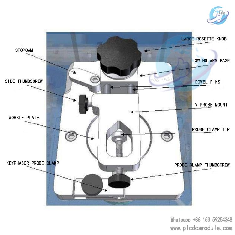
The swash plate imparts mechanical vibration to the eddy current probe. Changes in probe vibration can be observed by manually adjusting the position of the rocker assembly. When the rocker assembly is aligned with the center of the swash plate, the system generates the minimum vibration value; when the rocker assembly is moved to the edge of the swash plate, the maximum vibration value is produced. Since the swash plate is not at a 90-degree angle relative to the eddy current probe and the motor shaft, the rotation of the motor drives the swash plate to rotate, causing a change in the gap at the probe.
Composition of TK-3E
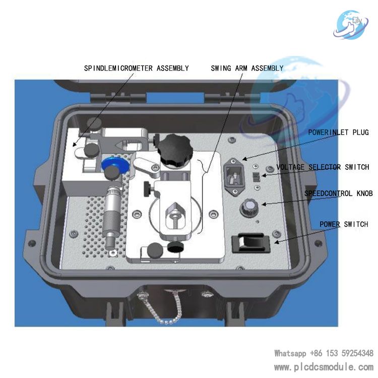
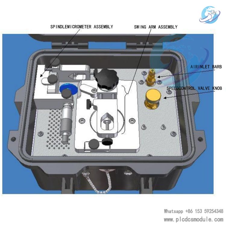
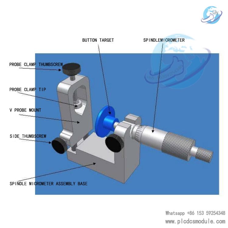
Components of the TK-3 front panel
Micrometer shaft assembly base
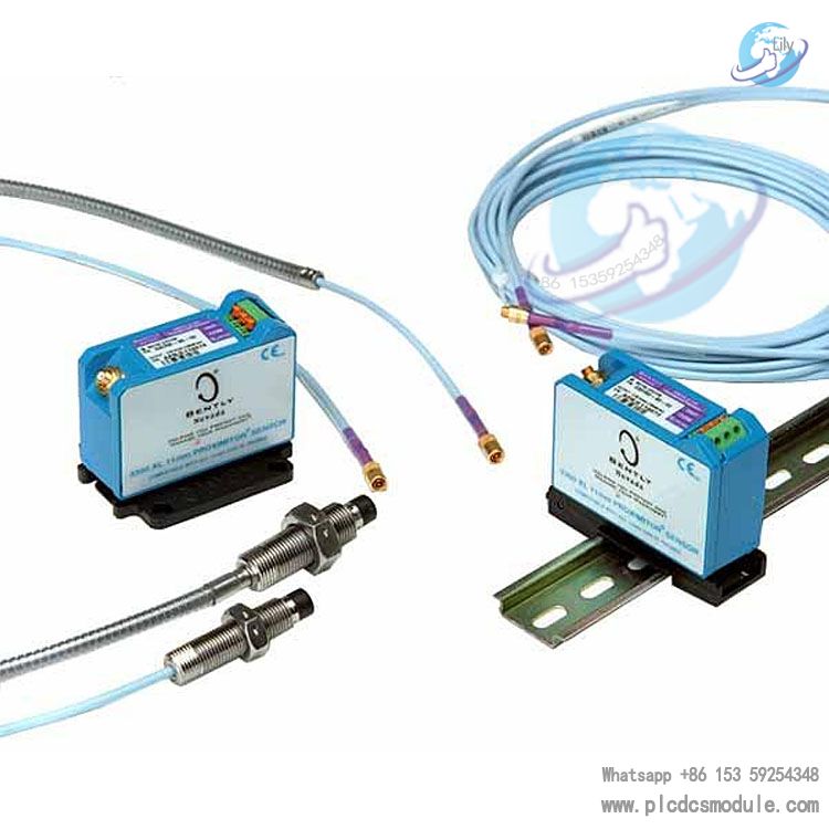
Probe, extension cable, preamplifier
Static characteristic verification of shaft vibration and shaft displacement probes
Instruments required for verification:
a. TK3-2E calibrator;
b. 4.5-digit digital multimeter;
c. 24V DC regulated power supply;
Inspection before verification:
• The probe and the composed cable assembly are complete and undamaged, the connectors are free of oxidation and rust, the protective layer at the end should have no signs of damage or peeling, the fasteners are complete and functional, and the junction box is undamaged.
• The extension cable is complete, without short circuit or open circuit, the connectors are free of oxidation and rust, and the protective layer is not damaged.
• The preamplifier is complete and undamaged, the mounting box has no falling off, deformation or poor sealing, and there must be a good insulating layer between the preamplifier and the mounting box.
Equipment connection diagram
 Condition monitoring calibration instrument.png")
Connect the equipment as shown in the above diagram. The preamplifier must be connected to the probe and the corresponding extension cable (with a total length of 5m). This step requires preparing an observation surface that has the same electrical properties as the observation surface of the monitoring system. Select an appropriate fixture, insert it into the probe, and place it in the fixed bracket.
 Condition monitoring calibration instrument.png")
Tighten and secure the micrometer, adjust the knob to indicate 0mm, gently press the top of the probe against the surface of the disc (taking care not to damage the top of the probe), and then tighten and secure the probe.
 Condition monitoring calibration instrument.png")
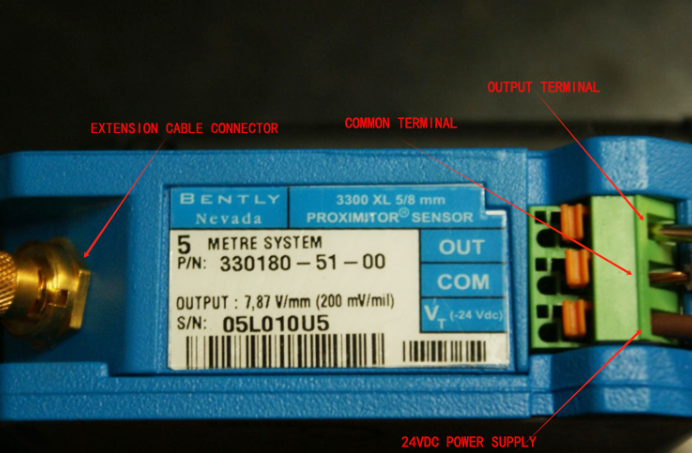
Connect the probe to the preamplifier via an extension cable. Connect the "-" terminal of the power supply to the -24VDC input terminal of the preamplifier, the "+" terminal of the power supply to the "COM" of the preamplifier, and connect the digital multimeter between "OUT" and "COM".
Turn on the power supply and adjust the gap between the micrometer and the top of the probe. Adjust the micrometer in the direction away from the probe. Within the linear region, for every 0.25 mm adjustment, the digital multimeter will show a voltage change of 2V (7.87V/mm).
Operating Process (Example)
Start with the micrometer knob indicating 0mm, increase the gap by 0.25mm each time, and record the corresponding output voltage value of the digital multimeter (this value is the output voltage of the preamplifier). Continue this until the micrometer indicates 3.5mm; this is the upward recording. Conversely, decrease the gap by 0.25mm each time based on the micrometer's indication, and record the corresponding output voltage value of the digital multimeter (this value is the output voltage of the preamplifier). Stop when the micrometer indicates 0mm; this is the downward recording. Organize and fill in the recorded data, and use the recorded data to draw the gap-voltage curve of the measured probe sensor system, which reflects the characteristics of the sensor.


 3005319639