


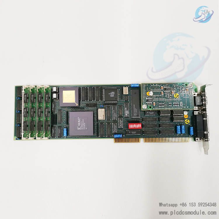
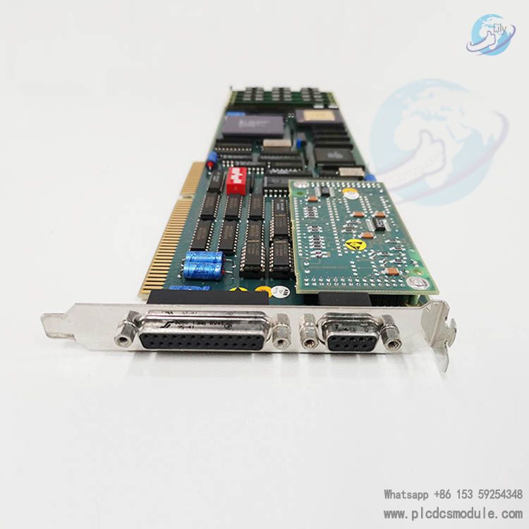
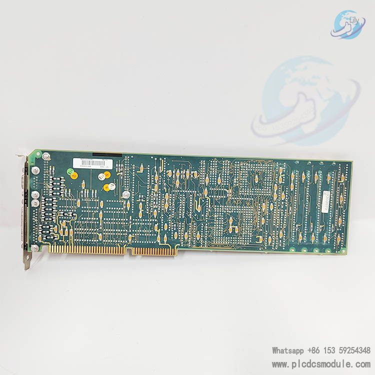
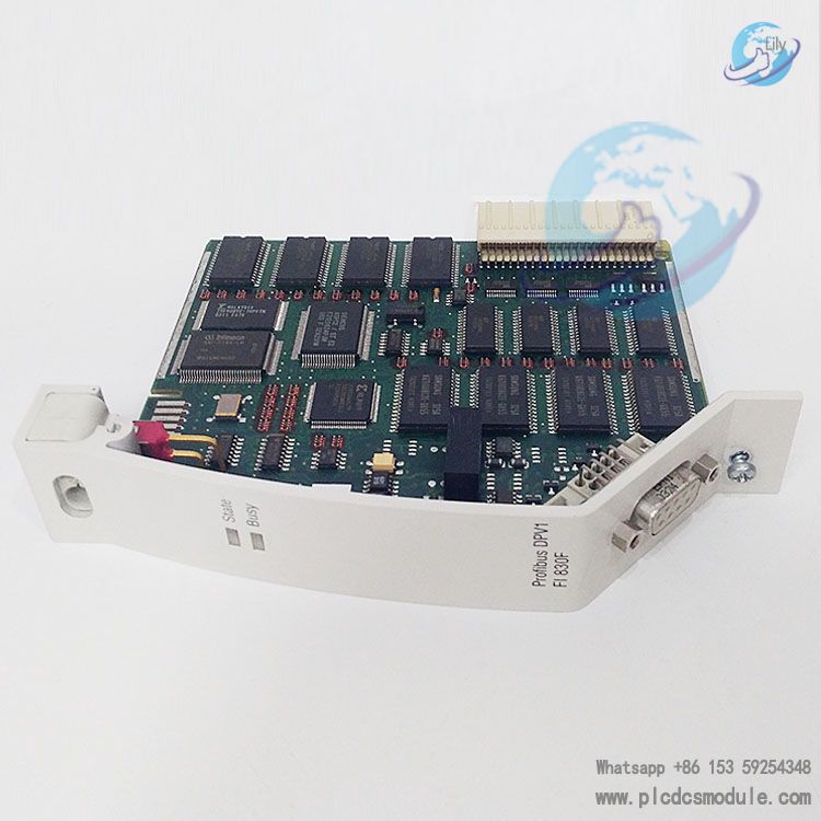
ABBDSPU 131 3BSE000355R1 MA200 Interface Board DSPU131.The ABB DSPU 131 MA200 interface board (product ID 3BSE000355R1) is a component designed for integration into the ABB Advant Master process control system. the DSPU 131 3BSE000355R1 interface board is customized for the AT-bus and has dimensions of 334.6 mm in length, 121.9 mm in height, 21 mm in width and weighs approx. 0.42 kg. It weighs approximately 0.42 kg.The DSPU 131 MA200 interface board is the key connection between the various components within the Advant Master system, enabling communication and data exchange. It is a small device, with external dimensions of no more than 50 cm, and falls into WEEE category 0, indicating that it does not contain a battery.
To learn more about this product click on the file below or download the file:
DSPU 131 3BSE000355R1 Installation Guide
(一) Installation Environment Requirements
Temperature and Humidity
Operating Temperature: Maintain the working environment temperature between 0°C and 50°C.
Relative Humidity: 5%–95% (non-condensing).
Avoidance: Do not install in high-temperature, high-humidity, or severely temperature-fluctuating environments to prevent impacts on equipment performance and service life.
Electrical Environment
Electromagnetic Interference (EMI): Install the device away from strong EMI sources (e.g., large motors, transformers) to avoid interference with data transmission accuracy and stability.
Grounding: Ensure the installation site has a good grounding system to prevent electrical faults caused by poor grounding.
(二) Installation Steps
Preparation
Power Off: Turn off the power supply of the relevant industrial control system.
ESD Protection: Wear anti-static gloves and other protective equipment to avoid damage to the device from static electricity.
Tools Ready: Prepare installation tools (e.g., screwdrivers).
Installation Location Selection
Choose a suitable position inside the industrial control cabinet to ensure adequate space for heat dissipation and convenient cabling/maintenance.
Install the DSPU131 near the main modules it connects to (based on the cabinet layout) to shorten cabling length and reduce signal transmission loss.
Equipment Fixing
Rail Mounting:
For DIN rail installation, securely clip the interface board into the 35mm standard DIN rail and ensure it is tightly locked to prevent loosening.
Screw Fixing: Use the provided screws to fasten the device. Tighten the screws firmly but avoid over-tightening to prevent damage to the housing or circuit board.
Cable Connection
MA200 Interface:
Ensure the plug and socket are tightly mated, fully inserted, and locked to avoid poor contact.
Other Interfaces (e.g., communication, power):Follow the labeling on the interfaces and the instructions in the manual for correct connection. Pay attention to cable polarity and connection sequence.
Frequently Asked Questions (FAQs)
1. What are the requirements for the installation environment?
Answer:
Temperature and Humidity: The recommended operating temperature range is 0°C to 50°C, with a relative humidity of 5% to 95% (non-condensing).
Electromagnetic Environment: Install the device away from strong electromagnetic interference sources (e.g., large motors, transformers) and ensure proper grounding.
Rationale: High temperatures may cause overheating and damage to the device; high humidity can lead to electrical short circuits; electromagnetic interference can distort data transmission; poor grounding may trigger electrical faults and pose risks to equipment and personnel.
2. How to correctly connect RS-485 and Ethernet interfaces?
Answer:
RS-485 Connection:
Pay attention to the polarity of wires A and B (do not reverse them).
Ensure the number of devices on the bus does not exceed the driving capacity of the RS-485 controller to avoid signal attenuation.
Ethernet Connection: Use standard network cables with properly crimped RJ45 connectors, and secure the plug in the interface to prevent looseness.
Configure the Ethernet interface with correct parameters (IP address, subnet mask, gateway, etc.) to ensure it is on the same network segment as other devices.
3.How to configure I/O points?
Answer:
Use ABB’s supporting programming software to configure I/O points:
Locate the corresponding DSPU 131 module in the software.
Define the function of each I/O point based on actual needs (e.g., set digital input points to receive sensor signals or analog output points to control valve openings).
Download the configured settings to the device to take effect.
4. How to set communication parameters?
Answer:
RS-485 Communication: Set parameters such as baud rate, data bits, stop bits, and parity bit to match those of the connected device.
Ethernet Communication: Configure parameters including IP address, subnet mask, gateway, and communication protocol (e.g., TCP/IP, UDP) to enable normal communication with other network devices.
What should I do if the device fails to start normally?
Answer:
Step 1: Check the power supply and measure whether the input voltage is within the specified range (generally ±10% of the rated voltage).
Step 2: If the power supply is normal, observe the status of the device’s indicator lights. Analyze potential causes (e.g., hardware damage such as chip failure or circuit board short circuits, or software program errors) based on the blinking pattern of the indicators. Contact ABB technical support for further troubleshooting and repairs.
How to resolve data transmission errors?
Answer:
Check Connections: Inspect for loose or damaged cables; re-plug or replace the cables.
Verify Parameters: Ensure communication parameters (e.g., baud rate, parity bit) are correctly set.
Eliminate Interference: Investigate potential electromagnetic interference and take measures such as using shielded cables or adding filters.
Advanced Troubleshooting: If the issue persists, the problem may stem from a faulty internal data processing module, requiring professional maintenance.
You may also use the following products on your project:
ABB LD800HSE 3BDH000320R02 FOUNDATION Fieldbus Linking Device
ABB GFD563A101 3BHE046836R0101 Central excitation controller
ABB KSD211B 3BHE022455R1101 Input Coupling Control Unit | KS D211 B
HONEYWELL 05701-A-0550 System 57 Controller
HIMA F8652X 984865265 Central module F 8652X
Bently Nevada 135489-02(3500/42M) I/O Module


 3005319639