Note; All products on this site are special products, the market price has been fluctuating, the specific customer service offer shall prevail, because the product is a new product, the picture is not a real shot, please confirm with customer service before placing an order model and product, price and other details, the site used, new are for sale, please contact customer service communication. The HIMA 62100 2-fold Analogue Limit Monitor is a modular monitoring device designed for safety-related applications. As an integral part of the HIMA Planar4 system ecosystem, it boasts core advantages of high safety, high flexibility and strong adaptability. Certified by TÜV, this product complies with the DIN V 19250 (RC 1-6) and IEC 61508 (SIL 3) safety standards. It is suitable for the precise monitoring and safety protection of analogue signals (current and voltage) in industrial settings, and can be widely deployed in scenarios requiring high safety integrity level monitoring such as chemical engineering, energy, and smart manufacturing. Its hardware adopts a dual-processor 1oo2 (1 out of 2) redundant architecture, combined with an independent electrical isolation design for inputs and outputs, which can effectively reduce the risk of single-point failures. Meanwhile, it supports parameterized configuration, real-time status display and multiple communication protocols, balancing safety and ease of use to meet the requirements for analogue signal limit monitoring, rate-of-change monitoring and redundant backup under different operating conditions.
related documents
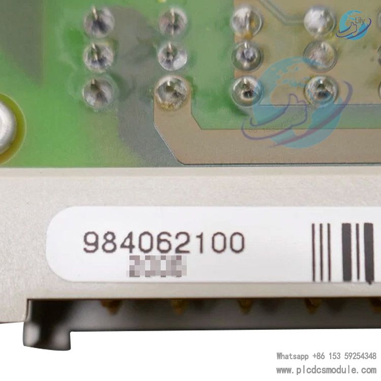
 HIMA 62100 984062100.pdf
Core Technical Parameters
The technical parameters of the HIMA 62100 cover key dimensions including input, output, accuracy and safety performance, ensuring its stable operation in complex industrial environments. The detailed parameters are as follows:
For input parameters, the input types include voltage input and current input. The voltage input ranges are 0...5.5V (without line diagnostics) and 1...5.5V (with line diagnostics); the current input ranges are 0...22mA (without line diagnostics, integrated with a 250Ω shunt) and 4...22mA (with line diagnostics). The measuring range complies with NE 43 standards: current > 3.6mA and < 21mA, with the voltage range matching accordingly. The input resistance is ≥100kΩ.
In terms of accuracy specifications, the reference error (+25℃) is ≤ 0.25% of the upper limit value; the operating error (-25...+70℃) is ≤ 0.4% of the upper limit value. The resolution is 12-bit (including the upper limit value of the overflow range), and the filtering constant is 10ms.
Regarding output parameters, there are 2 output channels with a maximum current of 100mA per channel. The current limit is 0.11A±10%, the internal voltage drop is 2.5V under maximum load, the minimum load is 12kΩ (light load is prohibited), and the maximum inductance is 1H. The safety time is 250ms. Line diagnostics can be parameterized and support short-circuit and open-circuit monitoring.
For the digital section, the switching time is < 250ms.
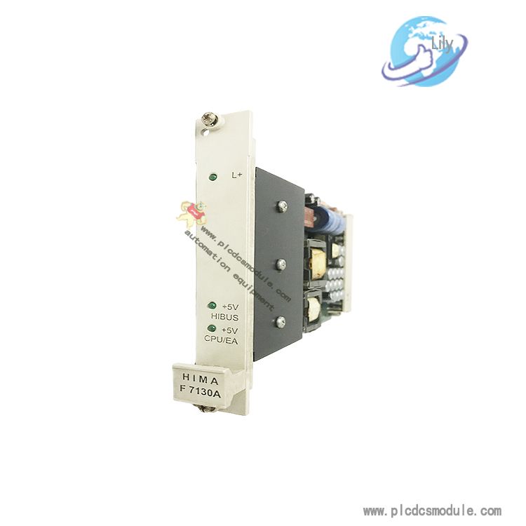
As for operating data, the power supply requirement is 24V DC with a power consumption of 170mA (excluding load). The installation dimensions are 3U in height and 4SU in width, suitable for 19-inch standard subracks.
For the fault indication relay, the switching voltage is ≤ 30V DC/AC with a minimum pick-up voltage of ≥ 10mV; the switching current is ≤ 1A with a minimum switching current of ≥ 10μA; the switching capacity is DC: ≤ 30W (for non-inductive loads) and AC: ≤ 60VA (cosφ>0.7). The bounce time is < 2ms. The service life includes mechanical life of > 10⁷ switching operations and electrical life (for resistive loads at ≤ 0.1 operations per second) of > 10⁵ switching operations.

Core Functions & Working Principles
1. Dual-channel Analogue Monitoring & Threshold Triggering
The HIMA 62100 supports two independent analogue inputs (voltage/current), and allows configuration of 2 threshold outputs for each input channel, achieving the flexible logic of one input channel corresponding to two threshold protection functions. Its threshold triggering logic is based on a threshold + hysteresis mechanism and supports two trigger direction configurations:
- Low Trigger (L-direction): The threshold output is de-energized when the input value falls below the set threshold; the output is re-energized when the input value rises back above threshold + hysteresis value.
- High Trigger (H-direction): The threshold output is de-energized when the input value exceeds the set threshold; the output is re-energized when the input value drops below threshold - hysteresis value.
Meanwhile, the module supports abnormal handling when the input signal goes beyond the standard range (< 3.6mA/0.9V or > 21mA/5.25V, compliant with NE 43). It can issue an alarm via the common Alarm signal output (z16), or trigger the ERR signal (output d28 and relay contact z26-d26 are disconnected) while shutting down all threshold outputs, thereby avoiding safety risks caused by abnormal signals.
2. Rate-of-change (Gradient) Monitoring
The module provides real-time monitoring of the rate of change of analogue signals. By configuring the variation and time range parameters, it can capture the rising, falling or absolute change trends of signals:
- Variation range: 0.5...110.0% for 0...20mA/0...5V inputs (at the maximum of 22mA/5.5V); 0.5...112.5% for 4...20mA/1...5V inputs (at the maximum of 22mA/5.5V), with a resolution of 0.5%.
- Time range: Selectable from 0.3s, 0.5s, 0.8s... up to 10s (step size of approximately 0.25s), with the total time range of all parameterized gradients not exceeding 20s.
- Trigger logic: When the signal rate of change exceeds the set value, the corresponding threshold output switches immediately. If the rate of change cannot be monitored (e.g., signal out of range), the z16 (Alarm) is triggered.
3. 1oo2 Redundant Sensor Collaboration (for RC 6/SIL 3 Scenarios)
For scenarios where RC 6 safety-related transmitters are unavailable, the module supports 1oo2 (1 out of 2) voting operation of two non-safety-related transmitters/sensors. It ensures safety by comparing the difference and time difference between the two-channel signals:
Data processing: The minimum, average or maximum value of the two sensor signals can be selected as the monitoring reference. Parameters includig
allowable difference (1.0...90.0%, resolution 0.5%) and allowable time difference (0.1...199.9s or 1...1999s, resolution 0.1s/1s) are configurable.
- Abnormal handling: When the difference between the two signals exceeds the allowable difference and persists for longer than the allowable time difference, the z16 (Alarm) is triggered first; after the timeout period, all relevant threshold outputs are shut down to avoid misjudgment caused by single sensor failure.
4. Parameter Configuration & Status Display
Parameter Configuration
No external PC or dedicated equipment is required; configuration can be completed via the 5 front-panel keys (MENUE, VALUE, ACK) and dual LCD displays. Configuration requires switching to PROG mode (the mode switch on the PCB must be adjusted by removing the module). For safety purposes, parameters cannot be modified during operation (RUN mode) and only the configured parameters can be viewed. During configuration, the same parameter must be entered and confirmed twice. If the parameter is out of range or the two entries are inconsistent, error codes E01 (threshold + hysteresis > allowable range) or E02 (threshold - hysteresis < allowable range) will be displayed to ensure configuration accuracy.
Status Display
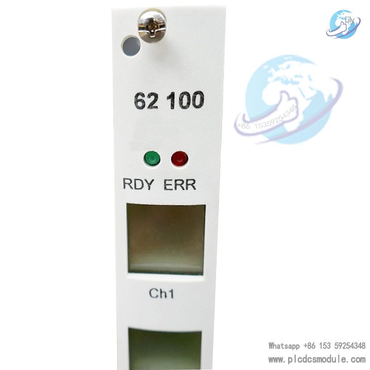
The front-panel LCD displays the digitized analogue values of the two channels with a resolution of 0.1% (0...110% corresponding to 0...22mA/0...5.5V; 0...112.5% corresponding to 4...22mA/1...5.5V). LED indicators (RDY, ERR) and icon status (steady on/flashing) provide intuitive feedback on the module status: for example, steady RDY indicates normal power supply (≥20V); flashing ERR indicates output line faults (open circuit/short circuit); illuminated icon borders indicate that the output is at logic 1, etc.
5. Communication & Redundancy Expansion
Communication Protocols
It supports two industrial communication protocols: MODBUS and Profibus-DP, enabling the upload of module status, input values, threshold parameters and other data. For instance, MODBUS function code 1 is used to read BOOL-type data, function code 3 for WORD-type data; Profibus-DP is used to read module type, actual values, output status, etc. This facilitates integration into Process Control Systems (PCS) for centralized monitoring.
Redundancy Expansion
To improve availability, the outputs of multiple 62100 modules can be paralleled (line monitoring must be disabled). For a single transmitter, redundancy schemes such as parallel input to two modules or series input to two modules (external 250Ω resistors and diodes are required for decoupling) can be adopted, ensuring that a single module failure does not affect the signals of subsequent logic circuits.
Installation & Safety Specifications
1. Installation Requirements
Physical Installation
The module shall be installed in a 19-inch standard subrack, occupying a space of 3U in height and 4SU in width. When used as a standalone system, its plastic housing ensures anti-interference performance, eliminating the need for additional shielding.
Wiring Specifications
Analogue inputs shall be connected to two electrically isolated signal sources or signal sources sharing a negative reference potential; connection to signal sources with different reference potentials is prohibited. Shielded cables (twisted-pair cables are recommended) shall be used for field input circuits. If the environment is free of interference and the cable run is short (e.g., inside a metal cabinet), shielding or twisted-pair cables may be omitted. However, shielded cables are critical to ensuring the anti-interference capability of analogue inputs.
Power Supply & Wiring
The 24V DC power supply circuit shall be routed separately from input/output circuits. In addition, measures against power failure, voltage fluctuation and under-voltage protection shall be implemented. The output circuit shall adopt two-pole connection.
2. Safety Operation Specifications
Limitations on Safety-related Functions
The z16 (Alarm), d28 (ERR) and fault indication relay contacts shall not be used for safety-related functions; they are intended for status feedback only.
Temperature Control
Temperature control measures (e.g., cabinet fans) shall be implemented outside the module to prevent excessive ambient temperature from affecting performance. The LCD display is only readable when the ambient temperature is above -10℃.
Fault Handling
In the event of a module fault (indicated by the ERR indicator turning on, d28 outputting a logic 1 signal, and z26-d26 relay contacts opening), the faulty module shall be removed or replaced immediately, and the fault event shall be recorded in the operation log. The module requires no routine maintenance and can be directly replaced upon failure.
Parameter Configuration Safety
Parameter configuration requires switching to PROG mode, during which all outputs will be de-energized. After configuration is completed, the module must be switched back to RUN mode to resume normal operation. Only parameter viewing is allowed during operation; parameter modification is prohibited.
3. Typical Application Scenarios
With its high safety integrity level and flexible configuration, the HIMA 62100 can meet diverse industrial monitoring requirements. Typical application scenarios include:
Single-channel Monitoring of Safety TransmittersOne channel is connected to a 4...20mA current-type safety transmitter, and the other to a 0...5V voltage-type transmitter. Threshold and hysteresis parameters are configured separately for each channel to achieve safety protection for two independent signals.
1oo2 Redundant Monitoring of Non-safety TransmittersTwo non-safety transmitters are deployed at the same measurement point and connected to the two channels of the module. The allowable difference and allowable time difference parameters are configured, and the reliability of measurement is ensured by comparing the two signals, meeting the requirements of RC 6/SIL 3 scenarios.
Redundant Backup of Analogue SignalsA single transmitter signal (0...5V voltage or 4...20mA current) is connected to two HIMA 62100 modules. The same threshold parameters are configured for both modules, and their outputs are paralleled to achieve single-signal dual-module redundancy, preventing monitoring interruption caused by module failure.
- Multi-threshold MonitoringA single transmitter signal is connected to both channels of the module simultaneously, and different thresholds (e.g., low threshold and high threshold) are configured for each channel, enabling multi-level safety protection for the same signal (such as dual-threshold alarm for excessively low and excessively high temperature signals).
Customers who purchased this product are also browsing the following products:
HIMA X-AI3201 985210213 Analog input module X-AI 32 01
HIMA F8652E Central Module F 8652E CPU 984865264
HIMA F8650X 984865065 Central module
HIMA H7202 985030008 power distribution module


 3005319639