


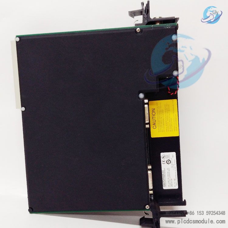
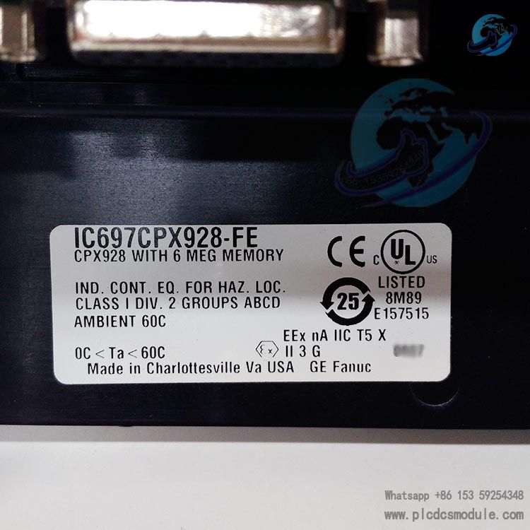
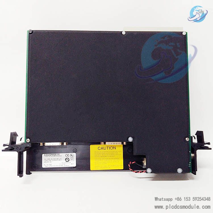
This module provides 6 MB battery-backed memory and 256 KB non-volatile user flash memory, specially designed for real-time control of machinery, processes, and material handling systems in industrial environments.It is compatible with IC660/IC661 and IC697 series I/O modules, supports VME C.1 standard backplane communication, and can be configured via programming software running on MS‑DOS or Windows 95/NT platforms.It supports floating-point arithmetic, password protection, remote programming, and online firmware upgrade functions, meeting the computing and expansion requirements of medium and large-scale industrial control systems. As a core control module in industrial automation, it delivers high reliability and fast processing speed.
Download
Core Technical Parameters
| Parameter | Specification |
|---|---|
| Part Number | IC697CPX928 |
| Series | GE Fanuc Series 90-70 |
| Processor & Calculation | 96 MHz 80486DX4 microprocessor, 32-bit floating-point arithmetic, Boolean function operation speed: 0.4 μs/unit |
| Memory Configuration | 6MB battery-backed CMOS RAM (program/config/register data), 256K non-volatile user flash memory; Flash-stored OS firmware supports online upgrade |
| I/O Support | Max 12K digital I/O (any combination), Max 8K analog I/O; Compatible with IC660/IC661, IC697 series I/O modules |
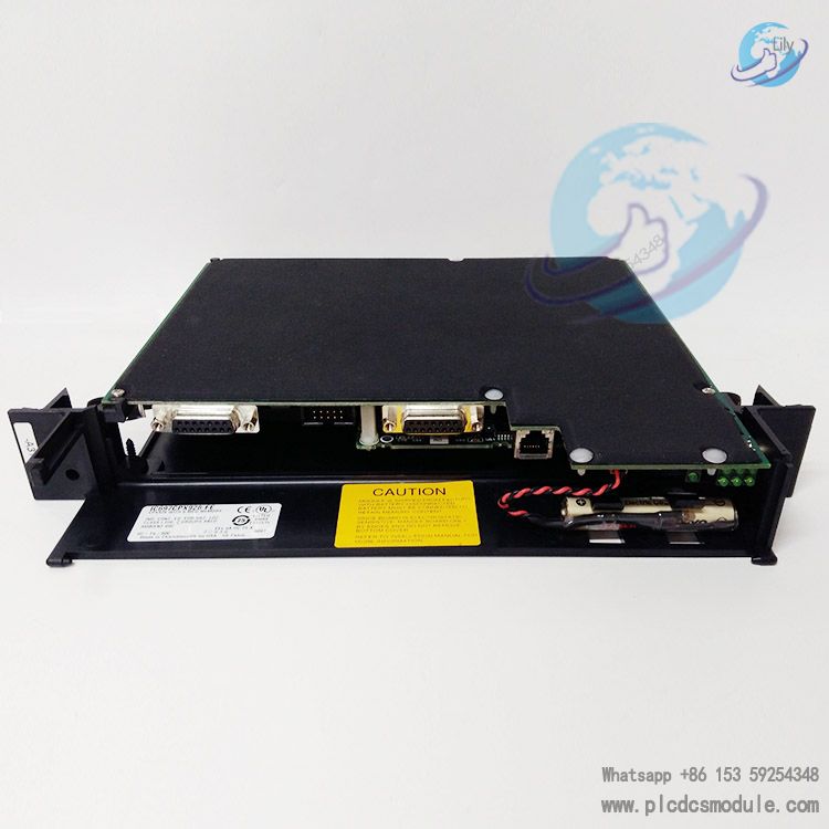
| Communication Capability | 3 serial ports (P1: RS-232; P2: optically isolated RS-485; P3: non-isolated RS-485); Supports SNP (Slave), Break-Free SNP (Slave, P1/P2) protocols; TCP/IP communication via IC697CMM741/742 Ethernet module |
| Operating Environment | Operating temp: 0~60℃ (32~140°F); No forced air cooling required ≤50℃, 70 CFM forced air cooling required >50℃; All racks need equipotential grounding |
| Power & Battery | 5V bus rated current: 3.1A; Standard IC697ACC701 lithium battery, 5-year shelf life at 20℃; Memory retention: nominal 6 months without power; Supports hot battery replacement |
| Clock Accuracy | Real-time clock max daily error: 3.5 seconds; Internal timing accuracy max: 0.01% |
| Physical & Protection | Only installable in slot 1 of rack 0; 3-position run mode switch; Dual protection: memory protection key switch + software password; 7 green status LEDs; No DIP switches/jumpers, pure software configuration |
| System Expansion | Supports up to 8 IC66* I/O racks; Max IC66* I/O bus transmission distance: 2285 meters (7500 feet); Max total length of interconnection cables from BTM to last BRM: 15 meters (50 feet) |
| Protocol & Standard | Compliant with VME C.1 standard; Supports BMA (Bulk Memory Area) (firmware version 7.92 and above) |
Key Functions and Features
Multi-mode Programming & Configuration
Supports parallel programming (MS‑DOS only), serial port programming, and Ethernet TCP/IP programming.
BMA function is supported in Windows software v2.2 and later; MS‑DOS software has limited functionality.
Multi-level Data Protection
When the memory protection key‑switch is locked, only the parallel‑connected programmer can modify programs/configuration.
Access is controlled by software passwords; battery‑backed memory ensures data retention during power loss.
Flexible Operation Control
Three‑position RUN/STOP switch supports three modes:
Run with Output Enabled
Run with Output Disabled
Stop
Operation status can also be remotely controlled via remote programmers and software.
Convenient Status Monitoring
Seven LED indicators provide real‑time status: module OK, run status, output enable, memory protection, and communication activity for three serial ports.
Module operation can be monitored without a terminal.
Online Firmware Upgrade
Connect to a compatible PC via serial port and run the firmware upgrade kit software to complete updates.
No module disassembly or EPROM replacement is required.
Hot‑swap Battery
Install the new battery before removing the old one to avoid memory data loss during replacement.
The battery also powers the calendar clock.
Installation & Usage Guidelines
Installation & Operation Rules
The module can only be installed in Slot 1 of Rack 0 of the Series 90‑70 rack.
Before installation, set the RUN/STOP switch to STOP, set the memory protection key switch to OFF, and turn off power to the rack.
When the ambient temperature exceeds 50°C, a 70 CFM forced‑air cooling fan must be installed below Slot 1 of the CPU rack.
Optional GE original fan assemblies: IC697ACC721 / 724 / 744.
For serial communication, ports P2 / P3 require a converter (e.g., IC690ACC901 cable kit). Custom cables are available for specific application requirements.
For Ethernet TCP/IP communication, an IP address must first be assigned to the IC697CMM741 / 742 module, then connect the programming PC to the PLC.
On power‑up, the CPU verifies module and rack configuration. If the actual configuration does not match the programmed configuration, a fault is reported to the alarm processor and the configured fault response is executed.
When removing the module, squeeze the plastic retaining clips on the backplane to release from the rack rail, then pull out smoothly along the slot to avoid damaging the backplane connectors.
GE Series 90‑70 Series Models
Original Accessories Ordering Information


 3005319639