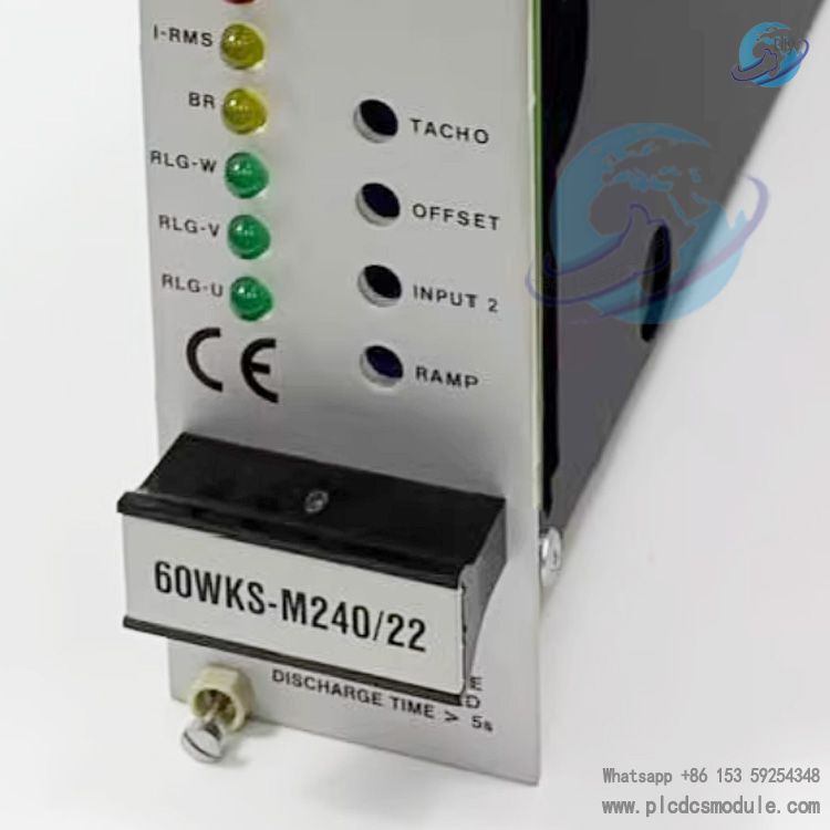
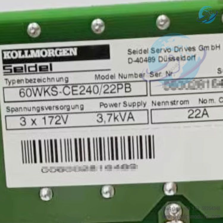
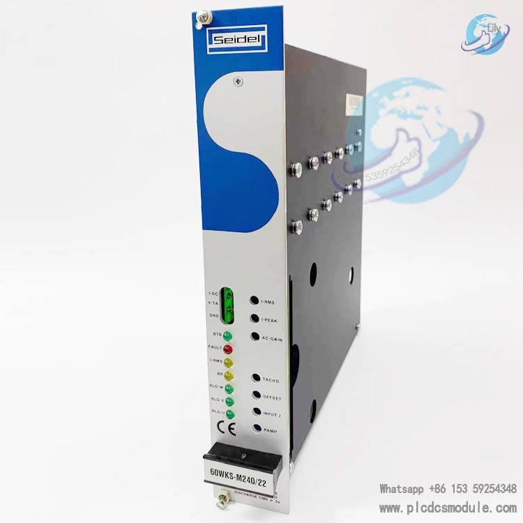
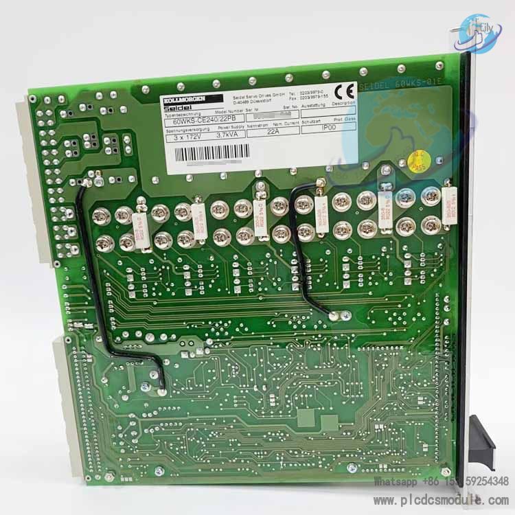
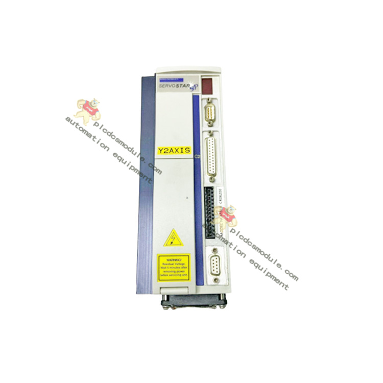
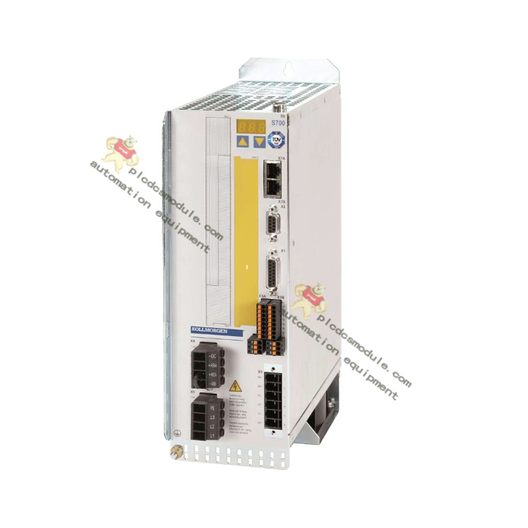
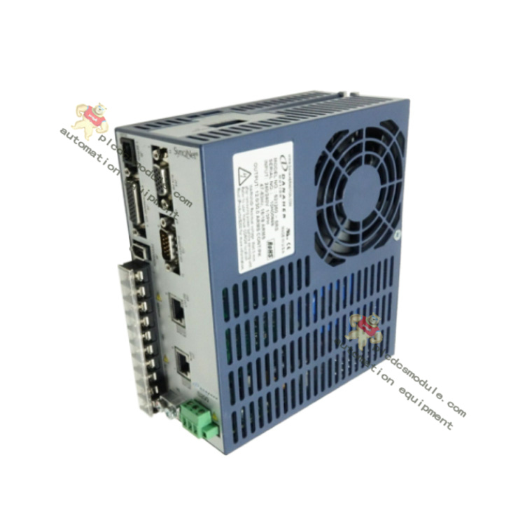
Note; All products on this site are special products, the market price has been fluctuating, the specific customer service offer shall prevail, because the product is a new product, the picture is not a real shot, please confirm with customer service before placing an order model and product, price and other details, the site used, new are for sale, please contact customer service communication. The 60WKS‑CE240/22PB is a classic 240V-class analog servo amplifier from Kollmorgen Seidel 60WKS series, specially designed for driving SM series brushless synchronous servo motors. It features four-quadrant PWM inverter output, trapezoidal commutation, and PI closed-loop control. Equipped with a built-in power supply, brake bleeder, comprehensive protection functions, and panel-adjustable parameters, it meets high-dynamic and high-precision speed/torque control requirements in machine tools, automated production lines, precision transmission systems, and other applications. Compliant with the CE Low Voltage Directive and EMC Directive, it is a proven model for industrial analog servo systems.
Position & Application
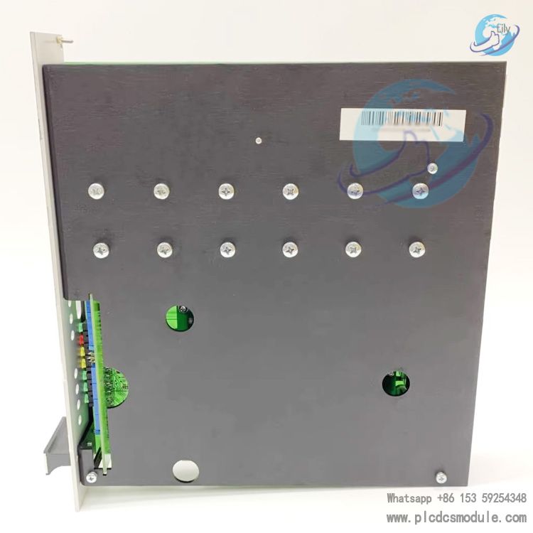
Compatible with: SM series brushless synchronous servo motors (with RLG rotor position sensor + tachometer feedback)Control type: Pure analog speed / torque closed-loop controlPower supply: Three-phase AC via isolation transformer → 240V DC busStructure: 19-inch card-type, double Eurocard format, suitable for cabinets / compact enclosuresTypical applications: Precision machine tools, packaging machinery, printing equipment, robot joints, test benches, and other high-precision motion control systems
Key Technical Specifications
1. Core Electrical Parameters
| Item | Value |
|---|
| Model | 60WKS‑CE240/22PB |
| Rated output current | 22A (continuous four-quadrant) |
| Peak output current | 50A (max. approx. 5s) |
| DC bus voltage | 240V DC |
| Input AC | 3×60–172V / 50–60Hz (+10%) |
| Output stage switching frequency | 2×8.5kHz |
| Current loop bandwidth | 1kHz |
| Minimum motor inductance | 0.7mH |
| Rated power consumption (including power supply) | 140W |
| Auxiliary output | ±15V/20mA (for sensors / feedback) |
2. Mechanical & Environmental
Dimensions: 220×233.4×45mm (double Eurocard, 9TE)Weight: 1.4kgOperating temperature: 0~+45℃ (derating + forced air cooling required above 45℃)Humidity: 5~85% RH (non-condensing)Protection: IP00 (must be installed in a closed electrical cabinet)Cooling: Forced air cooling for models ≥12A
3. Interfaces & Signals
Setpoint input: 2 channels of differential analog ±10V (SW1/SW2)Feedback interface: SubD 9-pin (RLG rotor position + AC/DC tachometer)Control interface: Enable, 1:1 mode, limit switches PSTOP/NSTOP (requires -01- option)Status outputs: BTB relay, I²t, IDC current monitoring, VTA speed monitoringDigital ground / analog ground: Separable via solder bridges for improved noise immunity
Features & Benefits
Four‑Quadrant Operation & Fast Response
Supports forward/reverse rotation, motor operation / regenerative braking, with fast dynamic response, ideal for frequent start‑stop and reversing applications.
One‑Touch Panel Potentiometer Tuning
No software required; direct adjustment of: ramp time, setpoint, offset, tachometer gain, AC gain, peak current, and RMS current.
Comprehensive Protection Mechanism
Full coverage protection against: overcurrent / short circuit, overvoltage / undervoltage, I²t thermal accumulation, power tube overheating, RLG / tachometer wire break, and auxiliary power supply failure.
Built‑in Brake Bleeder
Automatically activates discharge when bus voltage exceeds 285V, recovers braking energy, with no external brake unit needed.
High Noise Immunity & CE Compliance
Robust grounding, shielding and filtering design, complying with 89/336/EEC (EMC) and 73/23/EEC (Low Voltage Directive).
Flexible Option Expansion
- -01‑ Option Board: Ramp generator, 1:1 current follower, positive/negative limit switches
- -24V‑ Option: External 24V auxiliary power supply, maintains fault and BTB status even during power loss
Installation & Commissioning Guidelines
Power Supply
Must be connected via a three-phase isolation transformer (secondary side: 172V with shielded winding); direct mains connection is not permitted.
Wiring
Power cables: ≥4mm²Feedback / signal cables: twisted-pair shielded type, with shielding grounded over a large area and low impedance.
Safety
After power-off, wait at least 2 minutes and verify bus voltage is below 40V before plugging/unplugging or wiring.
Commissioning Procedure
- Reduce AC-GAIN and IPEAK to safe values
- Check bus voltage and auxiliary voltage under no-load conditions first
- Run at small setpoint after enabling
- Optimize offset, tachometer gain, control gain and current limiting
Ventilation
22A models require forced air cooling with unobstructed, dust-free air ducts.
Frequently Asked Questions (FAQ)
Q1: Motor does not move, no torque, BTB not lit?Check: Three-phase input, bus voltage, internal fuses F1/F2/F3
Verify: Enable signal, DGND grounding, solder bridge LB2 condition
Solution: Replace fuses with same rating, restore proper wiring and grounding
Q2: FAULT red light on, alarm shutdown?Causes: Overcurrent / short circuit, bus overvoltage, auxiliary power undervoltage, power tube overheating, feedback wire break
Solution: Check motor / cable short circuits; reduce braking frequency or increase bleeder resistance; inspect RLG / tachometer wiring; restart after cooling
Q3: Motor chattering, whistling, oscillation?Causes: Excessive AC‑GAIN, poor feedback shielding, AGND not connected, mechanical binding
Solution: Decrease AC‑GAIN counterclockwise; replace shielded cable; connect AGND to system ground at single point; check mechanical backlash and lubrication
Q4: Motor runaway / out of control?Causes: Incorrect motor phase sequence, RLG feedback wire break / reversed connection, abnormal tachometer signal
Solution: Verify phase and RLG wiring; replace feedback cable; recalibrate tachometer gain P304
Q5: I‑RMS yellow light always on, current limited?Causes: I²t effective current protection triggered due to excessive load or overset peak current
Solution: Increase IRMS (P307) appropriately; lower peak current IPEAK (P306); improve load conditions and cooling
Q6: Can a DC tachometer be used instead of an AC tachometer?Yes. Adjust solder bridges LB10/LB11/LB13 to DC position, and modify R310 or R301–R304 per manual to match voltage level.
Q7: What to note when powering on after long-term storage?For storage over 1 year,
capacitor reforming is required: first apply ≤ half rated voltage, gradually increase to activate bus capacitors, avoid capacitor failure or burst on power-up.


 3005319639