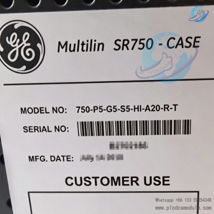
Note; All products on this site are special products, the market price has been fluctuating, the specific customer service offer shall prevail, because the product is a new product, the picture is not a real shot, please confirm with customer service before placing an order model and product, price and other details, the site used, new are for sale, please contact customer service communication. GE 750-P5-G5-S5-HI-A20-R-T is a
feeder management & protection relay from GE
Multilin (General Electric, USA), belonging to the customized variant of the base-model 750 series. Its firmware Version is V6.00 (officially released on Jan 05, 2004) with Hardware Revision J and Bootloader V4.00. The suffix -T denotes an optional factory-installed extended function. Each segment of the OEM ordering code corresponds to specific hardware specifications as below:
- P5: 5A phase current input
- G5: 5A zero-sequence ground fault current input
- S5: 5A sensitive ground current sampling
- HI: High voltage power supply (88~300VDC / 70~265VAC, 48~62Hz)
- A20: Eight-channel 4~20mA analog output
- R: Red LED indicator for circuit breaker close status
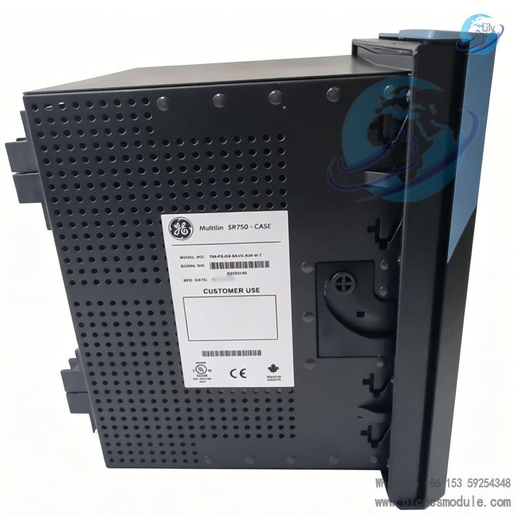
The unit is factory-equipped with an enhanced large-format E-type LCD display (model B screen is excluded when no "B" marking is present). It features identical enclosure dimensions for drop-in compatibility with legacy base-display 750/B models. Designed for 10kV ~ 35kV distribution feeders and auxiliary power outgoing circuits in industrial plants, this all-in-one protection & control device integrates fault protection, electrical metering, fault oscillography, remote communication and circuit breaker control functions. It serves as core equipment for rapid fault isolation of distribution feeders and on-site operational monitoring.
DOCUMENT DOWNLOAD
 GE 750-P5-G5-S5-HI-A20-R-T.pdf
Core Advantages
High Software & Hardware CompatibilityThe V6.00 firmware is fully compatible with all historical firmware versions ranging from 3.0x to 6.0x when paired with the EnerVista configuration software. Configuration files from the legacy 750PC can be imported directly without resetting protection settings during retrofitting of existing projects, drastically cutting construction man-hours.
Excellent Hardware VersatilityEnhanced (-E) and basic (-B) variants share identical mounting cutout dimensions and overall outline sizes. Replacement of old on-site devices requires no modification to cabinet cutouts or secondary wiring, enabling convenient field retrofit.
Cost Savings via All-in-One IntegrationA single unit integrates overcurrent protection, zero-sequence protection, sensitive earth fault protection, energy metering, fault oscillography and 8-channel 4~20mA analog output. It eliminates procurement expenses for standalone transmitters and separate fault recorders while reducing required cabinet space.
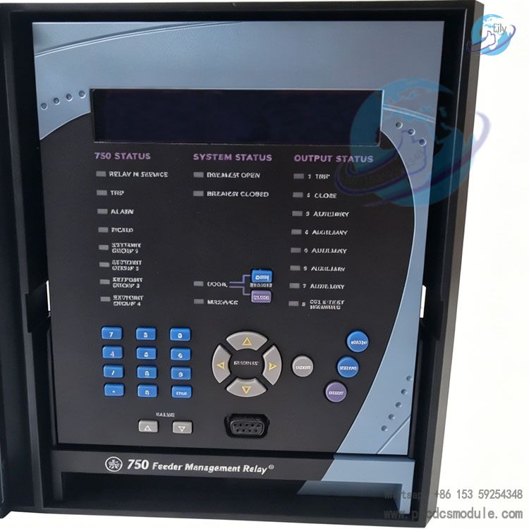
Optimized Human-Machine InterfaceThe revised V6.00 features a brand-new keypad layout: a dedicated MENU key replaces the original three keys (SETPOINTS/ACTUAL/NEXT), with directional MESSAGE keys for split up/down and left/right navigation. Equipped with large backlit LCD (40-character display), it facilitates quick on-site access to setting values and fault messages, and supports one-touch screen shutdown on front panel for power saving.
Efficient Commissioning & MaintenanceEnerVista is equipped with advanced oscilloscope for fault waveform analysis, Quick Connect serial communication and multi-device batch setting functions. A single software platform supports simultaneous commissioning of multiple 750/760 relays. It adopts dual-cursor waveform measurement with differential calculation and customizable playback sampling rate for intuitive fault tracing.
Wide-Range Power Supply with Superior Noise ImmunityThe HI high-voltage power option accommodates commonly used AC/DC control power supplies in industrial sites. The relay avoids unexpected shutdown or false tripping under voltage fluctuation and harmonic distortion conditions, suitable for harsh operating environments such as metallurgical and petrochemical plants.
Detailed Specifications
(I) Hardware & Electrical Specifications for 750-P5-G5-S5-HI-A20-R-T
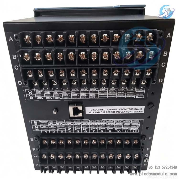
Current Sampling Circuits
- P5: 5A rated phase current input for three-phase overcurrent, overload and phase-to-phase fault protection.
- G5: 5A conventional zero-sequence current input to provide protection against high-magnitude system earth faults.
- S5: 5A high-precision sensitive earth current input designed for high-impedance earth fault monitoring on cable feeders, addressing the difficulty of detecting low-level earth faults.
Operating Power Supply (HI)
88~300 VDC and 70~265 VAC (48~62 Hz), compatible with DC control panels, UPS and auxiliary AC control power supplies commonly deployed in substations.
Analog Output (A20)
8 isolated channels of standard 4~20 mA industrial analog output. Three-phase current, voltage, active and reactive power can be transmitted to DCS and supervisory control systems with compatibility for mainstream industrial acquisition cards.
Status Indicator (R)
Dedicated red LED to indicate circuit breaker closed position; together with device fault alarm LEDs for local visual status check of breaker open/close status.
Display Panel
Enhanced backlit Type-E large-format LCD (40-character display). The V6.00 firmware removes the factory default backlight intensity setting with hardware-driven automatic brightness adjustment. It is equipped with a newly partitioned functional keypad:
- MENU: Toggle between setting values, measured readings and fault messages
- Left/Right MESSAGE keys: Submenu navigation
- Up/Down MESSAGE keys: Scroll within active submenu
- Numeric increment/decrement, Enter, Escape and Help keys; long-pressing HELP triggers full LED self-test.
(II) Functional Features of V6.00 Firmware
Protection Functions
Standard functions include definite-time/inverse-time overcurrent, instantaneous overcurrent, zero-sequence overcurrent, sensitive earth fault protection, thermal overload protection and under-voltage alarm. Automatic transfer switch (ATS) logic is available as an optional add-on; the auto-reclosing function exclusive to Model 760 is not equipped on the 750 series.
New Features of Supporting EnerVista Software
- Enhanced Fault Oscillography: Dual on-screen cursors (Cursor1/2) with Delta differential calculation, customizable waveform zoom and playback sampling rate for precise quantitative analysis of fault waveforms.
- Batch Configuration: Read and write setting values for multiple 750 relays in bulk within a single project workspace; view parameters, oscillography and event logs across concurrent windows.
- Quick Connect: Simplifies RS232 serial wiring and commissioning by eliminating complicated serial port parameter setup.
- On-Screen Display Toggle: Built-in one-touch backlight shutdown via menu to extend LCD service life during idle periods.
Data Logging
Sequence of Events (SOE) recording, fault trip oscillography, maximum demand and historical load storage. Revised maximum demand reset procedure for updated keypad layout: MENU → Decimal Point → Left MESSAGE (legacy path: Setpoint + Decimal Point + Up MESSAGE).
Communication Performance
Standard RS232/RS485 with optional 10Base-T Ethernet port; supports Modbus RTU/TCP and DNP3.0 protocols for seamless integration with power SCADA master systems.
(III) Version Improvements: V6.00 vs Legacy Firmware Releases
- Hardware: Upgraded to Type-E large LCD and optimized keypad layout while retaining identical overall dimensions and mounting cutout sizes.
- Software: Legacy 750PC configuration software is fully superseded by EnerVista; the fixed default backlight intensity setting is removed from firmware in favor of hardware adaptive backlight control.
FAQ
Q: What does suffix -T stand for in 750-R-T? Can the -T function be factory retrofitted afterward?A: -T refers to factory optional extended hardware and logic functions (including customized logic and special protocol licensing). These functions are fixed during manufacturing and cannot be added later via firmware upgrade. The -T option must be specified on the purchase order at ordering stage; units without -T are standard 750-R-E versions.
Q: Can existing legacy 750 relays with Type-B display be directly replaced by the Type-E display variant 750-P5-G5-S5-HI-A20-R-T?A: Yes. The V6.00 enhanced Type-E model shares identical mounting dimensions and secondary wiring definitions with older Type-B units for plug-and-play replacement. Only migrate setting files from legacy 750PC software to the latest EnerVista for parameter import.
Q: The site operating power is DC220V; should HI or LO power supply variant be selected?A: DC220V falls within HI specification range (88~300VDC), so HI model is mandatory. LO is rated for 25~60VDC / 20~48VAC and designed for low-voltage control supply applications.
Q: How to select between A20 and A5 analog output options for DCS requiring 4~20mA signals?A: A20 = 8-channel 4~20mA output; A5 = 8-channel 0~5mA output. As 4~20mA is the standard industrial signal for DCS acquisition, specify A20 exclusively.
Q: Relay powers up with functional LEDs but blank LCD screen; how to troubleshoot?A: ① Navigate front-panel menu to verify if display is manually disabled (Display OFF) and re-enable it;
② Replace Type-E LCD module if backlight is worn out;
③ Check loose wiring at internal backlight power terminals. V6.00 firmware eliminates backlight intensity setting parameters, no related setting modification required.
Q: EnerVista fails serial connection to 750 with Quick Connect unavailable; solutions?A: ① Use original GE dedicated programming cable instead of generic RS232 cable;
② Inspect front programming port for blockage by foreign debris;
③ Reboot relay and shut down PC serial port occupying software such as serial debug tools before reconnecting.
Q: How to retrieve fault oscillography and check fault current after protective tripping?A: Two available methods:
① Access fault oscillography menu via front-panel MENU to view simplified waveform locally;
② Connect EnerVista upper computer, upload oscillography files in one click and calculate peak fault current accurately via dual-cursor measurement tool.
Q: What is the new V6.00 keypad sequence to clear historical maximum demand?A: Updated operation path: MENU → Decimal Point → Left MESSAGE key. Legacy keypad procedure for old firmware is invalid and no longer applicable.


 3005319639