


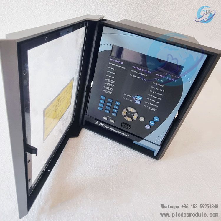

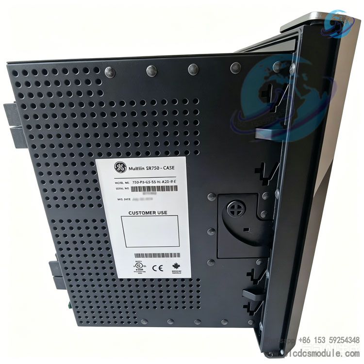
This model is configured with 5A phase current input, 5A residual current input, 5A sensitive earth current input, high-voltage power supply, 4-20 mA analog output, red circuit breaker status indicator light and enhanced Ethernet function. Adopting proven software and hardware architecture, it features high-precision protection, comprehensive monitoring, flexible communication and easy maintenance. It effectively reduces the total life-cycle cost of equipment, and is widely applicable to mainstream global power standards and complex operating conditions.
DOCUMENT DOWNLOAD
![]() GE 750-P5-G5-S5-HI-A20-R-E.pdf
GE 750-P5-G5-S5-HI-A20-R-E.pdf
![]() GE 750-P5-G5-S5-HI-A20-R-E Feeder Management Relay.pdf
GE 750-P5-G5-S5-HI-A20-R-E Feeder Management Relay.pdf
Product Features
1. Protection Functions
- Overcurrent Protection: Equipped with two-phase time-overcurrent (TOC) and instantaneous overcurrent (IOC). It covers phase current, neutral current, earth current and sensitive earth current protection. The current setting range is 0.005~20×CT. It supports 15 standard curves and user-defined curves, and features voltage blocking as well as instantaneous/linear reset functions.
- Earth Fault Protection: Integrates neutral instantaneous/time-overcurrent protection, earth instantaneous/time-overcurrent protection, sensitive earth protection and restricted earth fault (REF) protection. Adopting current-voltage dual polarization to distinguish forward and reverse faults, it is compatible with various earthing systems.
- Direction & Power Protection: Includes phase directional, neutral directional and earth directional overcurrent protection, as well as reverse power protection, which prevents reverse power feed from distributed generation and motoring operation of generators.
- Voltage Protection: Provides under-voltage, over-voltage, negative-sequence voltage and neutral point displacement voltage protection for busbars and lines. Tripping or alarm logic is configurable, with a voltage setting range of 0~1.25×VT.
- Frequency Protection: Fitted with 2 under-frequency elements and 2 over-frequency elements, plus 4 rate-of-change of frequency (df/dt) elements to stabilize grid frequency. The frequency measurement accuracy is ±0.02Hz.
- Auxiliary Protection & Control: Supports synchronism check (voltage, frequency and residual voltage verification), circuit breaker failure protection, cold load pickup, manual close blocking and busbar intertripping logic. The 760 series is additionally equipped with four-shot reclosing function.
2. Monitoring & Metering Functions
- High-Precision Metering: Real-time measurement of three-phase current, voltage, power, energy, power factor, phase sequence components and other parameters. It enables maximum demand and energy statistics, with a maximum metering accuracy of ±0.25% full scale.
- Equipment Condition Monitoring: Continuously monitors circuit breaker open/close status, trip faults, total arc current, temperature analog quantities and voltage transformer (VT) failures. A built-in trip counter records breaker operation times to predict equipment wear.
- Data Logging & Waveform Recording: Stores up to 256 event records with 1ms timestamp and a maximum of 10 fault waveforms. The sampling rate is 16 points per cycle, and data can be stored for up to 256 power frequency cycles. The built-in 8-channel data recorder supports data storage for up to 48 weeks.
- Fault Location: Calculates fault type, fault distance and line impedance via sampling data to quickly locate fault points.
3. Hardware & Interface Parameters
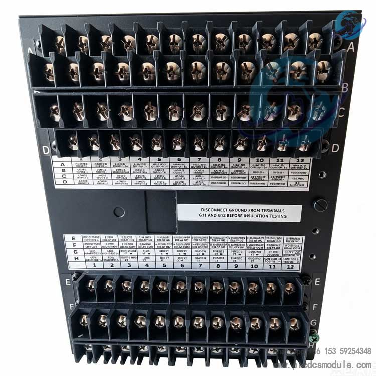
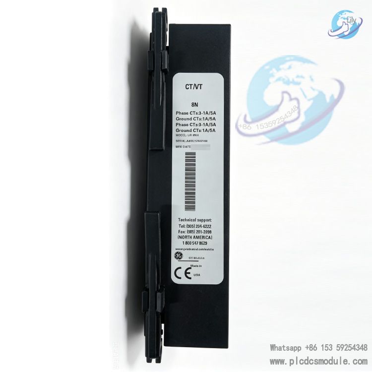
- Current & Voltage Input: Phase current, residual current and sensitive earth current are all rated at 5A. Voltage input adapts to 50~240V transformers with input load less than 0.025VA.
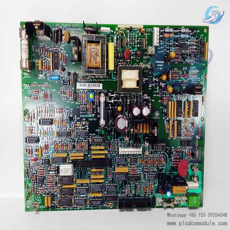
- Power Supply (HI High-Voltage Type): DC 88~300V, AC 70~265V (48~62Hz). Rated power consumption: 25VA; maximum power consumption: 35VA. Power-off hold time: 30ms.
- Output Interfaces: 8 electromechanical relay outputs (2 pre-configured for circuit breaker control, 1 for fault alarm), 1 high-speed solid-state output and 8 channels of 4-20mA analog outputs. All interfaces adopt full isolation design.
- Communication Interfaces: Front-mounted RS232 port, dual rear RS485/RS422 ports, and optional 10Base-T Ethernet. Baud rate: 300~19200bps. Supported protocols: Modbus RTU/TCP, DNP 3.0 Level 2.
- Environmental Adaptability: Operating temperature: -40℃ ~ +60℃; storage temperature: -40℃ ~ +85℃. Maximum operating humidity: 95% (non-condensing). Protection rating: IP40 (front), IP20 (rear). Optional three-proof coating for corrosive environments.
4. Supporting Software
Product Advantages
Optimized Overall CostIntegrated with high-precision metering functions, no additional auxiliary metering devices are required. The draw-out structure greatly cuts equipment replacement time. The built-in simulation function simplifies on-site commissioning, effectively reducing labor and time costs for operation and maintenance.
Application Scenarios
Main Protection for Distribution Feeders
Applicable to medium-voltage distribution feeders with solidly earthed, high-resistance earthed and resonant earthed (arc suppression coil) neutral systems. Acting as the primary line protection, it quickly isolates phase-to-phase and earth faults.
Backup Protection
Provides backup protection for substation busbars, power transformers and high-voltage transmission lines to establish a multi-layer protection system.
Automatic Grid Control
Supports busbar interconnection blocking/interlocking, automatic transfer of power supply and voltage/frequency-based load shedding logic, ensuring balanced grid load and continuous power supply.
Arc Fault Protection
Features high-speed fault detection to mitigate arc flash risks and enhance operational safety in power distribution rooms and switchgear cabinets.
Distributed Generation Grid Connection
Serves as protection at distributed generation (DG) grid connection points to prevent reverse power flow between utility grids and distributed power sources, guaranteeing safe grid interconnection.
Power Supply for Industrial Plants
Ideal for industrial internal ring main feeders and dual power switching systems. It isolates faulty feeders and prevents fault propagation.
FAQ
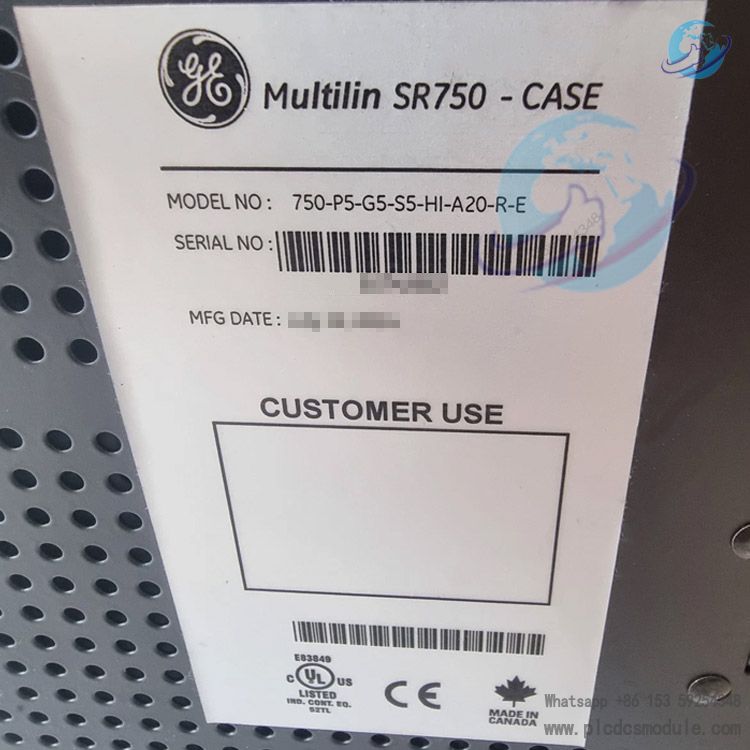
Q: What do the code segments of 750-P5-G5-S5-HI-A20-R-E stand for?
A: 750 refers to the product series. P5 = 5A phase current input; G5 = 5A zero-sequence current input; S5 = 5A sensitive earth current input; HI = high-voltage power supply (88~300VDC / 70~265VAC); A20 = 8 channels of 4-20mA analog output; R = red circuit breaker indicator light; E = enhanced panel plus optional Ethernet function.
Q: Can this model be used outdoors or in highly corrosive environments?
A: Yes. It supports optional three-proof coating. The operating humidity is up to 95% non-condensing, and the operating temperature ranges from -40℃ to +60℃, making it suitable for chemical plants, coastal areas and other humid and corrosive environments. No extra options are required for standard indoor switchgear applications.
Q: Do I need to purchase additional communication modules for procurement?
A: No extra modules are required. The device is standardly equipped with front RS232 port and rear RS485/RS422 ports. This model comes with optional Ethernet, and can be directly connected to SCADA and PLC systems simply by matching the corresponding communication protocols.
Q: Is it necessary to re-drill holes and rewire when replacing old GE SR series relays in existing cabinets?
A: No. GE provides dedicated retrofit kits for Series 8. The 750 series is fully compatible with original SR devices in terms of terminals and cabinet mounting holes. No changes are needed for pluggable terminals and on-site cables, and the replacement can be completed in as fast as 21 minutes.
Q: What items should be checked first if the relay trips falsely frequently?
A: First, check if the protection settings are set too low. Second, inspect for loose connections or damaged insulation on CT/VT wiring. Then verify the polarity of directional protection and polarization mode of earth fault protection. Finally, troubleshoot external electromagnetic interference, VT faults and transient system disturbances, and locate the cause with event and waveform records.
Q: How to troubleshoot communication failures between the monitoring system and the relay?
A: 1. Check whether communication cables, RJ45 and serial connectors are loose or damaged. 2. Verify that the protocols, baud rates, IP addresses and device addresses are consistent between the relay and the monitoring system. 3. Disable firewalls and check if communication ports are occupied. 4. Restart the relay and communication modules for retesting.
Q: How to export fault waveforms and event logs for failure analysis?
A: Connect the device via serial port or Ethernet using the supporting EnerVista software. Access the Wave Recorder / Event Log module to read and export waveform files in COMTRADE format and event reports locally. The latest 10 sets of fault data can also be viewed directly on the device panel.
Q: What causes the VT fault alarm during operation and how to resolve it?
A: A VT fault alarm indicates abnormalities in the voltage transformer circuit, commonly caused by blown VT fuses, loose or broken secondary wiring, and severe three-phase voltage unbalance.
Solution: Power off the device first, inspect the VT secondary circuit wiring and fuses, and measure three-phase voltages. Reset the alarm after eliminating circuit faults. If the alarm occurs repeatedly, calibrate the accuracy of the voltage transformer.


 3005319639