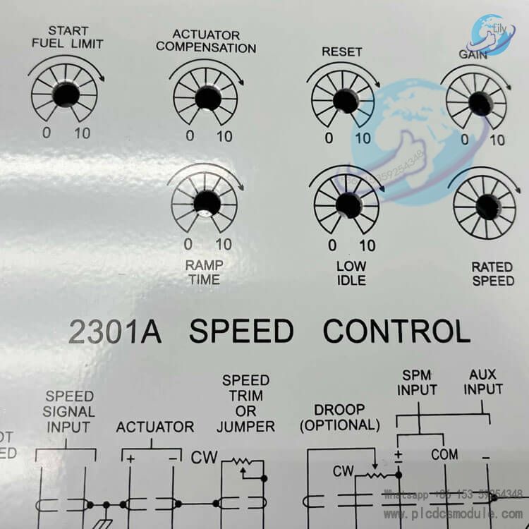
Woodward 2301A 9907‑014 Speed Control
Overview
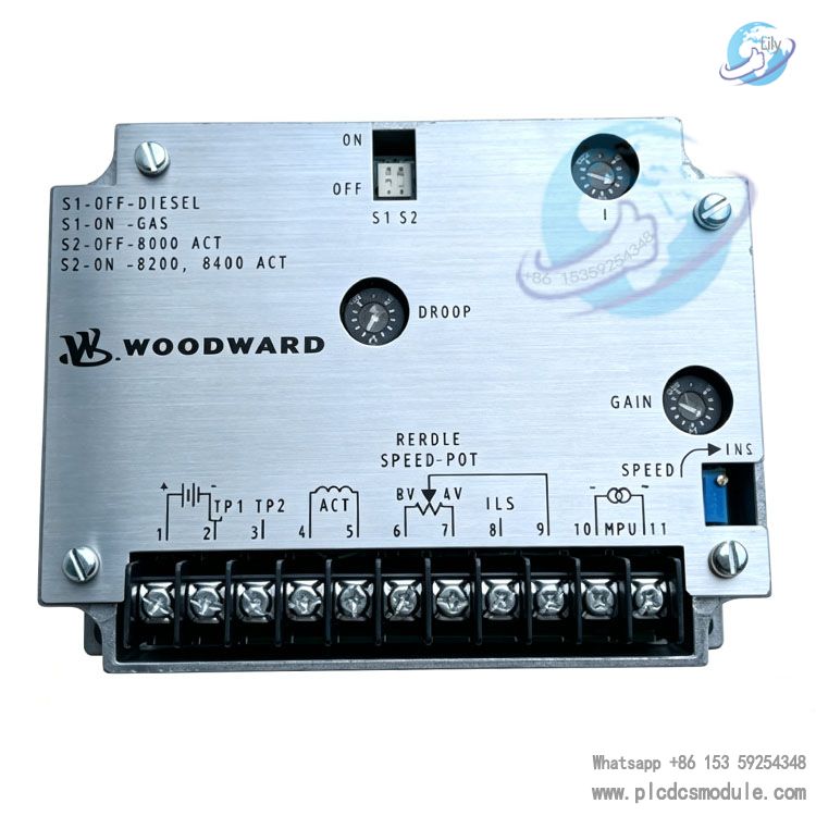
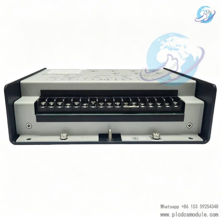
Woodward 2301A 9907‑014 is a low‑voltage forward‑acting electronic speed controller of the 2301A series, complying with EU directives. It is applied for speed regulation and load sharing of diesel engines, gas engines, steam turbines and gas turbines. Rotational speed signals are collected via magnetic pickup sensor. It supports switchover between isochronous mode and droop mode, suitable for unit standalone operation and multi‑unit parallel grid‑connected conditions. The 9907‑014 adopts sheet‑metal enclosure with all adjustment potentiometers arranged on the front panel. On‑site commissioning can be completed without opening the housing. It is widely deployed in industrial power generation, backup power supply and marine power control projects. For retrofit of legacy units, Woodward 2301A 9907‑014 can directly replace older models within the same series to minimize control cabinet modification work.

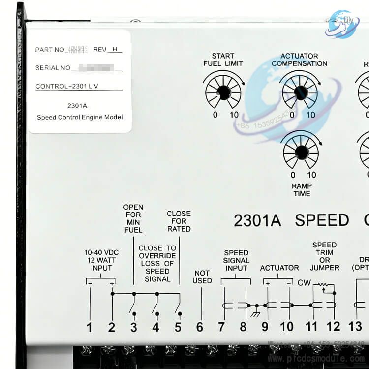
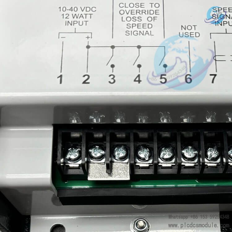
Technical Specifications
- Power Supply Input: 10‑40 VDC low‑voltage, power consumption 12W
- Actuator Output: Forward‑acting, 0‑200mA drive output
- Speed Signal Input: Magnetic Pickup (MPU), input voltage 1‑30Vrms, impedance 100‑300Ω
- Internal DIP‑Switch 4‑range frequency selection: 500‑1500Hz, 1000‑3000Hz, 2000‑6000Hz, 4000‑12000Hz; factory default: 2000‑6000Hz
- Operating Temperature: ‑40℃ ~ +85℃
- Enclosure: Sheet‑metal housing, surface‑mount type
- Droop Range: Max. 8% droop with external 2K potentiometer
- Speed Trim: ±5% speed offset via external 100Ω multi‑turn potentiometer
- Ramp Time: 1‑22 seconds adjustable from idle to rated speed; rated‑to‑idle deceleration less than 1 second
- Weight: Approx. 1.1kg
- Compliance: EU EMC and Low‑Voltage Directive compatible
Core Advantages
- Support isochronous zero‑droop speed control to maintain constant speed for standalone units; droop mode for multi‑unit parallel operation against infinite grid.
- Start fuel limit function to suppress black smoke during unit startup and optimize fuel supply at start‑up.
- Lost‑speed signal protection: minimum fuel command output upon speed sensor fault; external contact can temporarily bypass protection for turbine startup.
- Idle‑to‑rated speed acceleration ramp to restrain start‑up overshoot.
- Three dynamic potentiometers for gain, reset and actuator compensation to match dynamic characteristics of different prime movers.
- Support external speed trim, SPM‑A synchronizer and load sensor access for multi‑unit load sharing.
- Built‑in automatic circuit breaker for actuator short‑circuit and overheat protection; auto‑reset after hardware cooling.
All adjustable knobs on front panel for convenient field commissioning; analog‑circuit stability for harsh industrial sites.
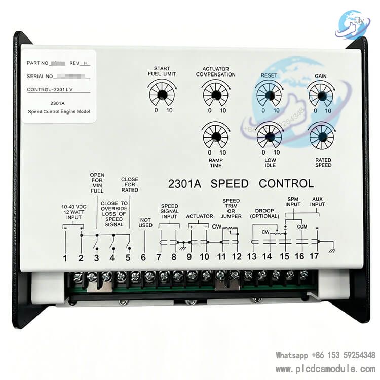
Product Features
- Single‑PCB integrated inside sheet‑metal enclosure with all adjustment knobs front‑facing.
- Low‑voltage DC power supply, compatible with 24VDC on‑board and marine power systems.
- Forward‑acting output: higher actuator current corresponds to increased fuel delivery.
- A complete governing system requires external magnetic pickup sensor (MPU) and proportional actuator; the controller cannot work independently.
- Shielded twisted‑pair cable is required for signal wiring; shield shall be single‑point grounded only at the controller side to mitigate speed fluctuation caused by electromagnetic interference.
- Direct mounting on engine body is prohibited; install inside control cabinet to avoid vibration and high temperature.
Application Fields
- Speed governing and parallel load sharing for diesel generator sets and gas generator sets.
- Land‑based standby power stations and marine auxiliary power generation.
- Speed control for gas turbines and steam turbines.
- Retrofit & upgrade projects for legacy governing systems.
Power control systems for multi‑unit island‑bus parallel operation and public‑grid interconnection.
Working Principle
- Magnetic pickup (MPU) collects gear rotational speed and outputs frequency signal to Woodward 2301A 9907‑014. Internal frequency‑to‑voltage converter converts frequency into DC voltage and compares it against internal reference speed voltage.
- Deviation between actual and reference speed drives amplifier to output corresponding current to actuator, adjusting fuel or steam valve opening until actual speed matches set‑point speed.
- External load sensor signal is fed into auxiliary terminals to realize load sharing under isochronous mode for parallel units. External droop potentiometer enables speed‑droop function, where speed decreases proportionally as load rises for grid‑parallel operation.
- Lost‑speed protection triggers when speed signal falls below threshold and outputs minimum fuel command; external momentary contact can bypass protection for turbine start‑up sequence.
- Gain adjusts speed fluctuation amplitude upon load disturbance; reset adjusts speed recovery rate; actuator compensation compensates hysteresis of actuator and prime mover.
Cross‑Model Comparison
| Model | Power Supply | Action Type | Key Differences |
| 9907‑014 | 10‑40VDC Low‑Voltage | Forward‑acting | EU‑compliant, standard 0‑200mA output, for general standalone & parallel applications |
| 9905‑131 | 10‑40VDC Low‑Voltage | Forward‑acting | Non‑EU version, identical hardware functions to 9907‑014 |
| 9907‑016 | 10‑40VDC Low‑Voltage | Reverse‑acting | Reverse output: fuel increases with dropping actuator current, for EGB‑type actuators |
| 9905‑132 | 88‑132VAC High‑Voltage | Forward‑acting | High‑voltage AC/DC supply, for cabinets without 24VDC power source |
Compatible Supporting Parts
- Actuators: EG‑3P, EG‑6P, EG‑10P proportional actuators
- Speed Sensor MPU: Magnetic Pickup
- Synchronizer: SPM‑A synchronizer matching module
- Load Sensor: Woodward Load Sensor module
- External Droop Potentiometer: 2KΩ potentiometer
- External Speed Trim Potentiometer: 100Ω ten‑turn potentiometer
Recommended Related Models
- 9907‑014 2301A Speed Control
- 9905‑131 2301A Speed Control
- 9905‑133 2301A Speed Control
- 9907‑016 2301A Speed Control
- 9905‑132 2301A Speed Control
- 9905‑134 2301A Speed Control
- 9905‑135 2301A Speed Control
- 9905‑137 2301A Speed Control
- 9905‑136 2301A Speed Control
- 9905‑138 2301A Speed Control
- 9905‑448 2301A Speed Control
- 9907‑015 2301A Speed Control
- EG‑3P Actuator
- EG‑6P Actuator
- SPM‑A Synchronizer
Technical Document Notes
- Reference Manual: Manual 82020 Revision D, 2301A Speed Control Installation & Operation Manual. Read ESD protection chapter fully before commissioning; release human‑body static electricity before disassembly‑assembly.
- Only ONE DIP‑switch position shall be set ON simultaneously; multiple ON‑positions will cause speed‑recognition error.
- Controller shall NOT be mounted directly on prime mover body.
- Independent overspeed shutdown protection device must be configured; the controller shall NOT serve as overspeed protection.
FAQ
Q1: Can Woodward 2301A 9907‑014 directly replace 9905‑131?
A1: Yes. Hardware wiring is fully compatible. 9907‑014 adds EU compliance certification while potentiometer parameters, terminal definitions and DIP‑switch settings remain identical.
Q2: Can 9907‑014 controller drive engine standalone? What extra accessories are required?
A2: It cannot work alone. Complete system requires magnetic pickup speed sensor, proportional actuator and DC power supply. For parallel load sharing, load sensor or droop potentiometer is additionally needed.
Q3: Unit speed oscillates and hunts during operation. Which knobs should be adjusted first?
A3: Lower GAIN first, then adjust RESET. If oscillation persists, fine‑tune Actuator Compensation potentiometer, meanwhile verify wiring shielding and grounding status.
Q4: Is 9907‑014 a reverse‑acting controller?
A4: No. 9907‑014 is forward‑acting; higher output current delivers more fuel. Select 9907‑016 for reverse‑acting requirement.
Q5: What voltage level does speed sensor need for valid speed detection?
A5: During barring and startup, MPU output shall reach minimum 1Vrms and shall not exceed 30Vrms. If voltage is excessively high, increase gap between sensor and gear tooth.
Q6: How to select high‑voltage or low‑voltage version for procurement?
A6: Choose low‑voltage 9907‑014 if stable 24VDC is available inside control cabinet. Select high‑voltage model 9905‑132 without low‑voltage DC source. Never feed high‑voltage power into low‑voltage controller, otherwise hardware will be permanently damaged.
Q7: Low idle speed cannot be adjusted via LOW IDLE knob, what is the fault?
A7: Most possible cause: idle setting is below actuator minimum‑fuel mechanical limit. Adjust actuator linkage to lift mechanical minimum‑fuel position. Second, inspect wiring status of external idle / rated contact terminals.
Q8: Ramp Time knob is set to maximum value, yet deceleration from rated to idle remains very fast.
A8: The ramp function of 2301A applies ONLY to idle‑to‑rated acceleration. Deceleration from rated speed down to idle is NOT governed by RAMP TIME knob; deceleration time is fixed below 1 second, which is inherent product characteristic.