


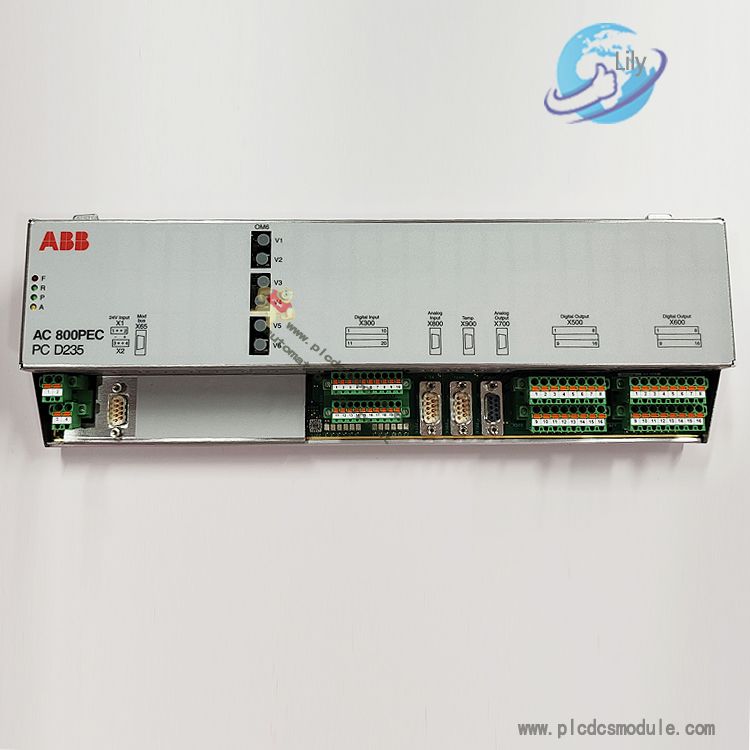
The ABB PCD232 A0101 3BHE022293R0101 PEC80-CIO is an integrated general-purpose input/output controller module. It belongs to the ABB AC80 PEC control platform and serves as the core universal interface unit of the UNITROL 6000 excitation control system. This module integrates digital I/O, analog I/O, temperature acquisition and various communication interfaces, and features control, signal acquisition and data interaction capabilities.
The PCD232 A0101 incorporates the PEC80-CU control module, PEC80-PM processor module, PEC80-PS power supply module and PEC80-OM optical module, fully equipped with all software functions of the PEC80 control system. It supports dual redundancy configuration. With an independent watchdog circuit, wide-temperature operating performance and industrial-grade protection design, it can operate stably for a long time under harsh industrial conditions, and is a critical hardware component for excitation systems and automatic control in power generation, heavy industry and other fields.
Product Features
1. Signal Channel Configuration
Temperature Acquisition Interfaces: 3 channels, compatible with PT100 RTDs and PTC thermistors, adopting 3-wire measurement mode.
Digital Input (DI): 12 isolated digital control inputs divided into 2 groups (6 channels per group). It supports 24V/48V voltage signals, with each group equipped with an independent 24V sensing power supply. The typical current per channel is 6mA.
Digital Output (DO): 16 relay output channels. Contact switching voltage: 250VAC; switching current: 10A; contact isolation test voltage: 500V.
Analog Input (AI): 3 universal analog input channels, supporting ±10V voltage and ±20mA current signals. Load resistance: 50Ω; accuracy: less than 1% FSR.
Analog Output (AO): 3 analog output channels with an output range of ±10V and maximum output current of 5mA. Accuracy: less than 1% FSR.
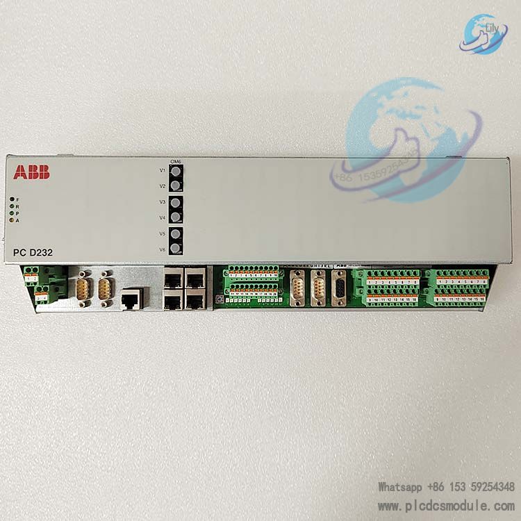
2. Communication & Display Interfaces
Ethernet: 4-port 10/100 Mbps auto-adaptive Ethernet switch ports, supporting network cascading and multi-device networking.
Serial Ports: RS232 (dedicated for control panel), RS485 (Modbus protocol) and CAN bus interfaces.
Optical Module: 1 optical module port with 3 optical fiber links, enabling long-distance and anti-interference optical signal transmission.
Status Indicators: 4 system control LED indicators for real-time display of module operation, fault and communication status.
3. Power Supply & Address Parameters
Power Supply: Redundant 24VDC power supply. Rated voltage range: 20~28V; maximum supply current: 2A.
Device Address: Module address range: 0~15, supporting address assignment for multi-module networking.
4. Hardware & Reliability Specifications
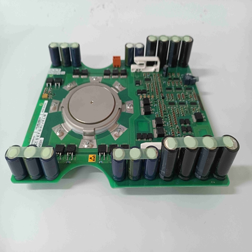
Core Architecture: Built on the AC80 PEC control platform, featuring an all-in-one design integrating processor, control unit, power supply and optical module.
Reliability: Reliability index of 7076 FIT at 40°C. A built-in independent watchdog enables automatic system recovery from faults.
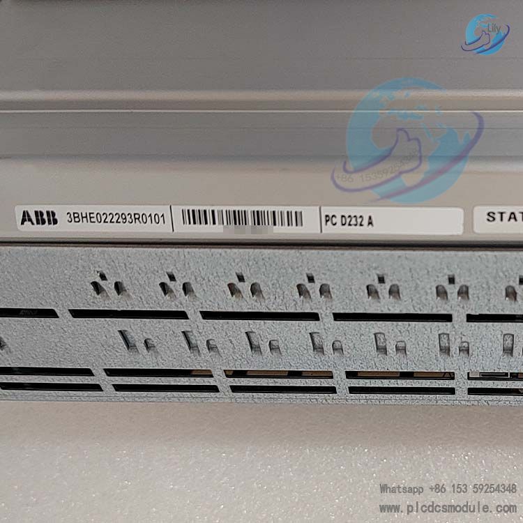
Version Information: Standard model: PCD232 A01; ABB part number: 3BHE022293R0101.
Core Advantages
High Integration & All-in-One Signal Processing
A single module integrates temperature, digital and analog signal acquisition and output, as well as multiple communication interfaces. It enables connection of various signals without additional expansion modules, simplifying cabinet layout and cutting wiring and hardware costs.
High Reliability & Redundant Design
Dual PCD232 A devices support full-system interface redundancy. The built-in independent hardware watchdog effectively prevents program runaway and system downtime. Redundant 24V power input greatly enhances power supply stability, ideal for critical applications requiring non-stop operation.
Wide Operating Range & Strong Environmental Adaptability
The operating temperature ranges from -25℃ to +70℃, suitable for harsh environments such as low-temperature outdoor sites and high-temperature equipment rooms. All signal channels adopt electrical isolation, and relay outputs feature a 500V isolation withstand voltage, delivering excellent anti-electromagnetic interference performance.
Multi-protocol Communication & Superior Compatibility
Equipped with Ethernet, RS232, RS485 (Modbus), CAN and optical fiber links, the module can connect to local control panels, host systems and fieldbus devices simultaneously. It seamlessly integrates with all ABB control systems and third-party industrial networks.
Excellent Measurement & Control Accuracy
Both analog input and output accuracy are better than 1% FSR. The 3-wire measurement for PT100/PTC sensors and 2kHz analog input bandwidth fully meet the requirements of high-precision and high real-time control scenarios.
Application Industries
As the standard I/O unit for the UNITROL 6000 excitation system, this module is mainly applied to power generation and supplemented by industrial automation. Its key application sectors are listed below:
Power Industry (Core Sector)It is deployed in generator excitation control systems of thermal power, hydropower, nuclear power and gas power plants to regulate generator voltage and reactive power, and collect and monitor rotor temperature as well as operational status.
Heavy Manufacturing IndustryApplied to excitation and drive control systems for large synchronous motors in process industries including iron & steel, papermaking, chemical engineering, oil and gas refining.
Industrial AutomationServes as remote I/O acquisition stations for large-scale DCS and PLC systems, realizing centralized collection of on-site temperature, digital and analog signals as well as control output.
Rail Transit & New EnergyFunctions as a signal interaction and control unit for large generator sets, energy storage power stations and vehicle-mounted high-power excitation equipment.
Frequently Asked Questions
Q: What is the complete order code of PCD232 A01? What model distinctions should be noted during procurement?A: The standard product name is PEC80-CIO with model PCD232 A01 and official order number 3BHE022293R0101. This is the standard version with no sub-models. Please verify the ABB part number to avoid confusion with other derivative models of the PCD232 series.
Q: Can this module be purchased separately? What is the minimum order quantity and delivery lead time?A: It is available for individual purchase, with the standard minimum order quantity of 1 unit. The standard delivery time from the manufacturer varies by stock status: 3 to 7 working days for in-stock items, and 3 to 4 weeks for backorders.
Q: Can this module directly replace the legacy I/O modules of the old UNITROL 6000 system? Is program modification required?A: As a standard accessory for the UNITROL 6000 system, it features fully compatible hardware pins and communication protocols, supporting direct hardware replacement. No program changes are needed if no custom channel logic is applied in the original system. Only module address and channel configuration need to be checked.
Q: The module operates on 24V, but only 220V power is available on site. What additional accessories are required?A: The module requires redundant 20~28V DC power supply. If no DC power is available, install industrial-grade 220V AC to 24V DC switching power supplies. Two independent power supplies must be configured for redundancy. Single power supply is prohibited to ensure the redundant function works properly.
Q: The operation LED stays off and the module fails to respond after power-on. How to troubleshoot quickly?A: 1. Check the two 24V redundant power inputs and confirm the voltage is within 20~28V; inspect broken wires and loose terminals.2. Verify the module is properly installed with good contact on the DIN rail.3. Power off, remove and reinsert the module to resolve hardware stuck issues.4. If power supply is normal but the module still does not work, the internal power unit is likely faulty and factory repair is required.
Q: Analog input signals (±20mA/±10V) show large deviation and fluctuation. How to solve this problem?A: 1. Check channel settings in the configuration software to ensure consistency between on-site signal type (current/voltage) and software configuration.2. Ground the shielded cables with single-point grounding; multi-point grounding will cause interference.3. Avoid routing signal cables alongside power cables, as strong electric interference leads to signal fluctuation.4. Calibrate channel zero point and full scale. If the error persists, the analog channel hardware is defective.
Q: The 16 relay output channels fail to drive loads and the relays do not act. How to troubleshoot?A: 1. Measure the voltage across relay contacts to determine whether the fault lies in the module output or the load circuit.2. Check if the load exceeds specifications (single-channel current ≤10A, voltage ≤250VAC). Overload will trigger contact protection lockout.3. Check the fault LED for overcurrent or isolation breakdown alarms.4. Connect a small external load for testing. If the relay still does not act, the contacts are damaged and the module needs replacement.
Q: Communication disconnection and Modbus/CAN bus dropout occur in multi-module networking. What are the troubleshooting steps?A: 1. Check module addresses and ensure no duplicates within the range of 0~15.2. Test cable continuity and confirm terminating resistors are installed in compliance with specifications.3. Lower the baud rate to eliminate signal attenuation caused by long-distance transmission.4. Check surrounding equipment to rule out strong electromagnetic interference.5. Test communication with a single module separately to locate the faulty module and cable.


 3005319639