


Product Overview
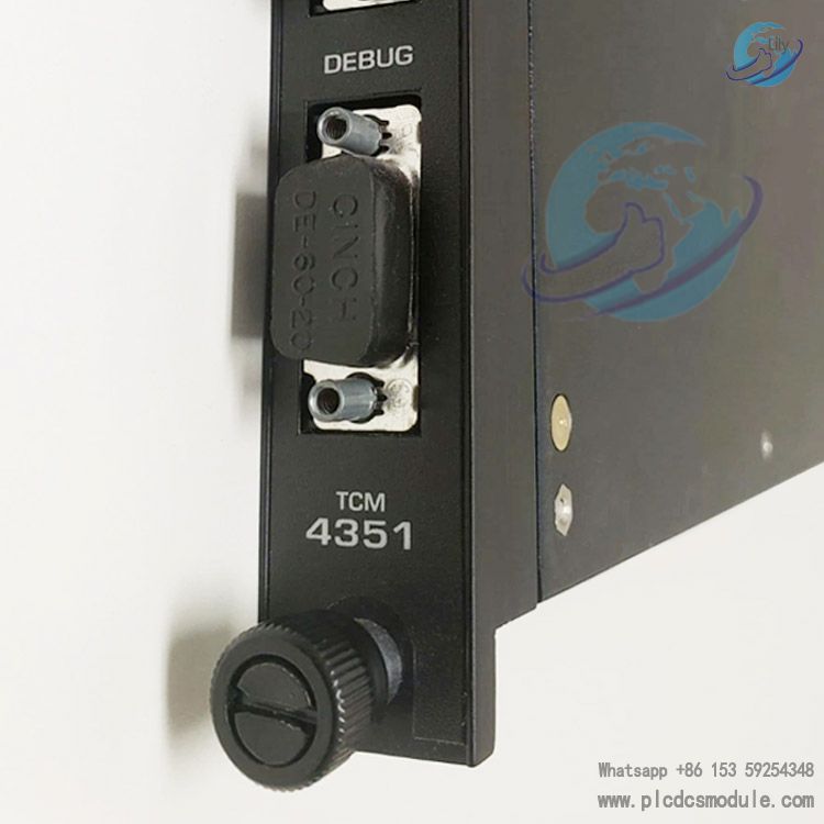
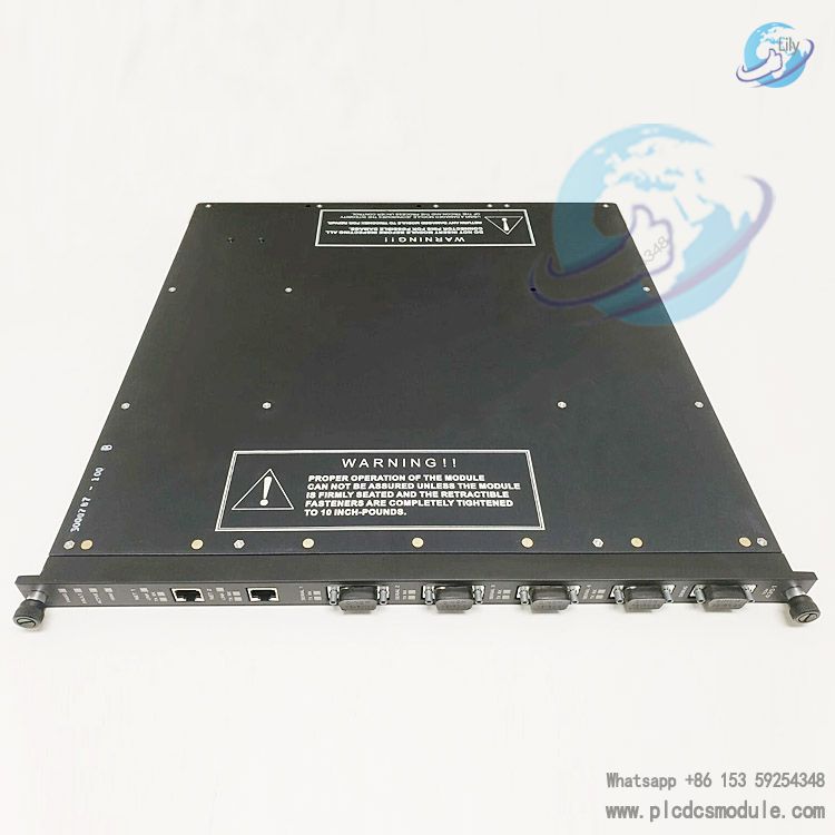
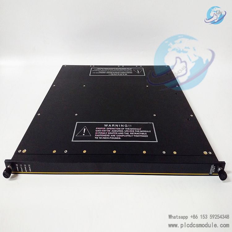
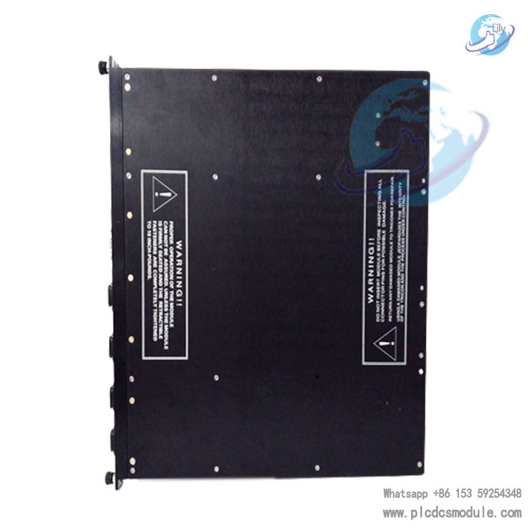
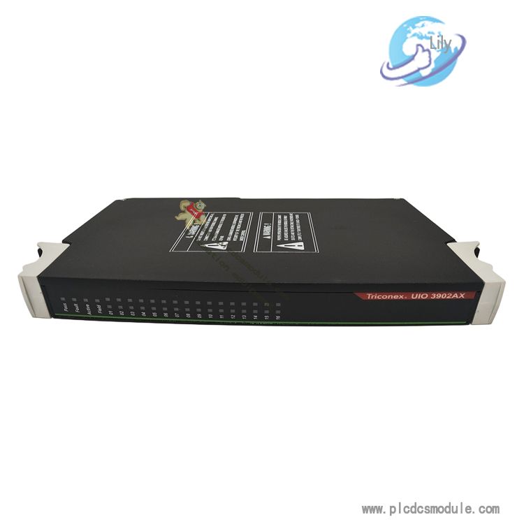
The TRICONEX TCM 4351 is a high-availability Ethernet communication module designed exclusively for Triconex Safety Instrumented Systems (SIS), providing reliable data exchange between safety controllers and plant-wide automation systems. It supports redundant communication paths to ensure uninterrupted operation in critical applications.
Equipped with dual 10/100/1000 Mbps Ethernet ports, the TCM 4351 enables seamless integration with Modbus TCP, OPC UA, DNP3, and IEC 61850 protocols, making it ideal for oil & gas, petrochemical, power generation, and other process industries requiring SIL 3 safety certification.
With hot-swappable design and built-in diagnostic capabilities, the module minimizes downtime and simplifies maintenance, while its rugged construction ensures reliable performance in harsh industrial environments with extreme temperatures and electromagnetic interference.
Key Specifications
- Model NumberTCM 4351
- Communication Ports2 x 10/100/1000 Mbps Ethernet
- Supported ProtocolsModbus TCP, OPC UA, DNP3, IEC 61850
- Safety CertificationSIL 3 (per IEC 61508)
- RedundancyDual-port redundant path
- Form Factor3U CompactPCI (cPCI)
- Operating Temp Range-40°C to +70°C (-40°F to +158°F)
Technical Specifications
| Category | Parameter | Details |
|---|---|---|
| Hardware | Form Factor | 3U CompactPCI (cPCI) - Single slot width |
| Dimensions (W x H x D) | 100mm x 132mm x 250mm (3.94" x 5.20" x 9.84") | |
| Weight | 0.8 kg (1.76 lbs) | |
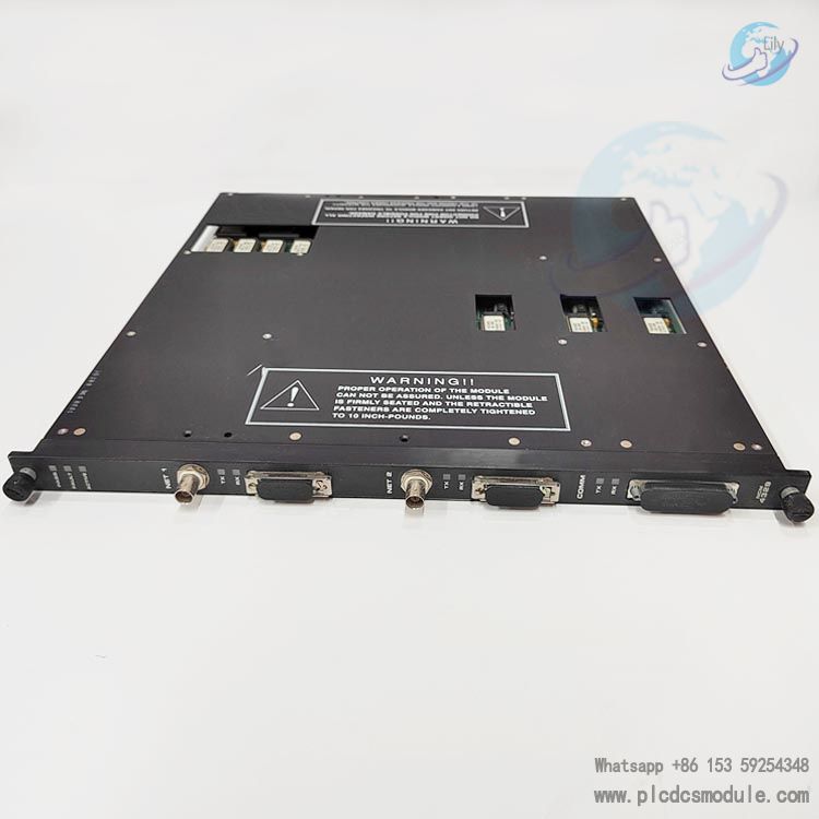
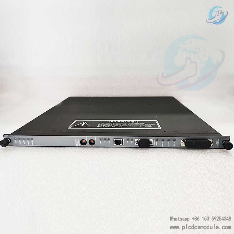
| Communication | Ethernet Ports | 2 x RJ45 ports (10/100/1000 Mbps auto-negotiation) |
| Supported Protocols | Modbus TCP (client/server), OPC UA (client/server), DNP3.0 (level 2), IEC 61850 (MMS/GOOSE) | |
| Maximum Connections | 64 concurrent TCP/IP connections | |
| Redundancy | Dual-port redundant path, automatic failover (< 100ms) | |
| Environmental | Operating Temperature | -40°C to +70°C (-40°F to +158°F) |
| Storage Temperature | -40°C to +85°C (-40°F to +185°F) | |
| Humidity | 5% to 95% non-condensing (IEC 60068-2-3) | |
| EMC Compliance | EN 55022 Class A, EN 55024, IEC 61000 | |
| Electrical | Power Supply | 5V DC ±5% (from cPCI backplane) |
| Power Consumption | Max 15W (typical 10W) | |
| Isolation | 2.5kVrms between Ethernet ports and backplane | |
| LED Indicators | Power (green), Port 1 Link/Activity (green), Port 2 Link/Activity (green), Fault (red) | |
| Certifications & Compliance | Safety Certification | SIL 3 (IEC 61508:2010), TÜV Rheinland certified |
| Hazardous Area | ATEX, IECEx, Class I Div 2, Zone 2 | |
| Environmental Compliance | RoHS, REACH, WEEE |
Compatibility Information
The TRICONEX TCM 4351 is fully compatible with Triconex safety controllers and selected Schneider Electric automation systems. Below is the detailed compatibility list:
Important Note: For optimal compatibility, ensure the Triconex controller firmware is updated to the latest version (≥ 11.0 for 3600/3700/3800 series, ≥ 12.0 for 4100/4200 series). Contact Schneider Electric technical support for firmware upgrade assistance and compatibility verification with specific third-party systems.
Installation Instructions
Safety Warning:Before installing or servicing the TCM 4351 module, ensure the Triconex controller is powered off and disconnected from all power sources. Follow proper lockout/tagout (LOTO) procedures to prevent accidental power-up. Only qualified personnel with appropriate training should perform installation and maintenance.
Pre-Installation Preparation
Verify that the installation environment and equipment meet the module's requirements:
- Ensure the Triconex controller is powered off and LOTO procedures are in place
- Check that the controller backplane slot is compatible (3U cPCI slot)
- Inspect the module for physical damage (e.g., bent pins, cracked housing)
- Verify the module firmware version is compatible with the controller (≥ v5.0)
- Prepare the required tools and Ethernet cables (Cat5e or higher)
Tools Required:
Module Installation
Install the TCM 4351 module into the Triconex controller backplane:
- Put on the anti-static wristband and connect it to a grounded surface
- Align the module with the guide rails of the designated cPCI slot
- Gently slide the module into the slot until it makes contact with the backplane connector
- Secure the module to the controller chassis using the front-panel screws (torque to 0.5 N·m)
- Ensure the module is fully seated and the front panel is flush with the controller chassis
Ethernet Cable Connection
Connect the Ethernet cables to the module's RJ45 ports:
- For redundant communication, connect both Ethernet ports (Port 1 and Port 2) to separate network switches
- Use Cat5e or Cat6 Ethernet cables (maximum length: 100 meters)
- Ensure the cables are securely plugged into the RJ45 ports (listen for a "click" to confirm proper connection)
- Label the cables for easy identification (e.g., "TCM 4351 Port 1 - Switch A")
Power-Up and Initial Verification
Power on the controller and verify the module's operational status:
- Remove the LOTO devices and power on the Triconex controller
- Observe the module's LED indicators:
- Power LED (green): Should illuminate within 30 seconds
- Port Link/Activity LEDs (green): Should illuminate if the Ethernet cable is connected to a powered switch
- Fault LED (red): Should remain off (illumination indicates a fault)
- Use the Triconex Configuration Software (e.g., TriStation 1131) to verify the module is detected by the controller
Configuration and Testing
Configure the module and test communication:
- Launch the Triconex configuration software and access the TCM 4351 configuration menu
- Set the IP address, subnet mask, and gateway for the module (static IP recommended for safety systems)
- Configure the desired communication protocols (Modbus TCP, OPC UA, etc.) and connection parameters
- Perform a communication test with the target system (e.g., SCADA, PLC) to verify data exchange
- Test the redundant path (if applicable) by disconnecting one Ethernet cable and confirming failover
Related Products
Triconex 3721 Digital Input Module
16-channel digital input module for Triconex TMR safety systems, SIL 3 certified
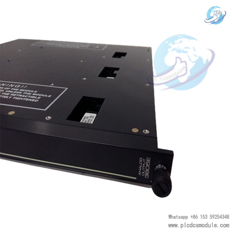
Triconex 3805E Safety Controller
Enhanced triple-modular redundant (TMR) controller with high processing capacity
Triconex 4351B Communication Module
16-channel digital input module for Triconex TMR safety systems, SIL 3 certified
Triconex 3625 Power Supply Module
Redundant power supply module for Triconex controllers (24VDC, 10A output)


 3005319639