


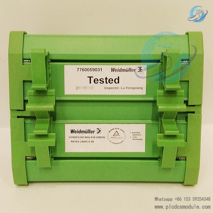
Triconex 9662-810 is a 16-point common-terminal digital output terminal panel specially designed for 24 VDC digital output modules, and it belongs to the supporting product series of the Tricon v9–v10 systems.
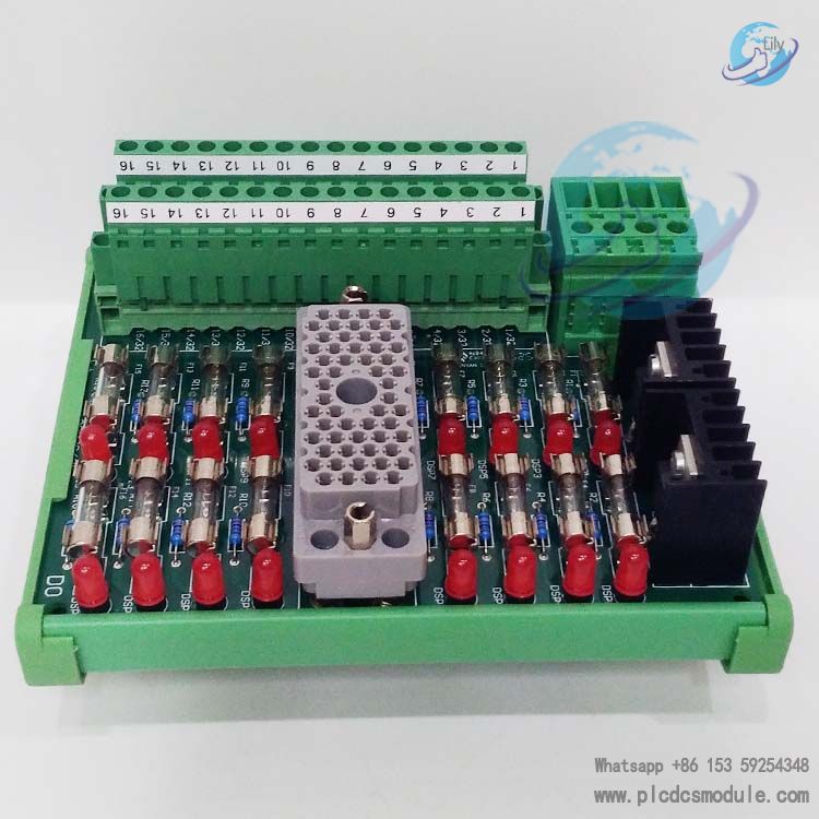
Featuring a common-terminal design, the panel is equipped with 16 load terminals and common power terminals (PWR+ and PWR–). Each output point is provided with a fuse and a fuse indication function, which can offer reliable circuit protection and status monitoring for the connected digital output modules. Widely applicable to industrial control scenarios requiring stable digital signal output, it builds a safe and efficient bridge for the connection between the system and on-site devices.
related documents
Specifications
| Feature | Description |
|---|---|
| Panel Type | Commoned |
| Number of Output Points | 16 points |
| Maximum Total Current | 16 A |
| Rated Voltage | 24 VDC |
| Protection Configuration | Each output point is equipped with a fuse, with a blown-fuse indicator |
| Terminal Configuration | 16 load terminals + common power terminals (PWR+, PWR–) |
Compatible Modules
The Triconex 9662-810 Terminal Panel is only compatible with specific models of 24 VDC digital output modules. Detailed compatibility information is shown below:
| Module Model | Number of Points per Module | Module Description | Main Fuse Specification |
|---|---|---|---|
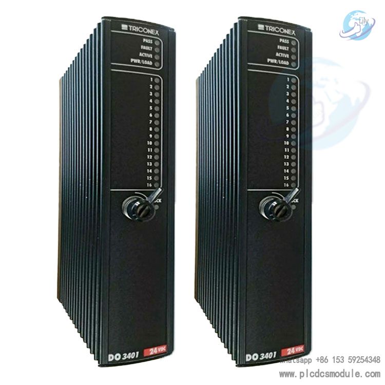
| 3604E | 16 | 24 VDC, Non-commoned, Optically Isolated, Triple Modular Redundancy (TMR) | 2.5A, Fast-acting Type |
Core Functions & Design Highlights
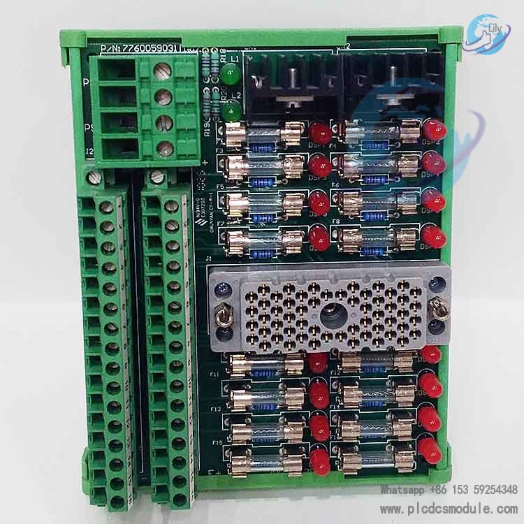
- Reliable Circuit ProtectionEach output point is fitted with an independent fuse, which effectively protects the module and panel from damage caused by faults such as overload and short circuit. Combined with a blown-fuse indicator, it allows for intuitive monitoring of fuse status, facilitating quick fault diagnosis and improving maintenance efficiency.
- Commoned Power Supply DesignThe PWR+ and PWR– common power terminals simplify the power wiring process and reduce wiring complexity. Meanwhile, they ensure stable and consistent power supply for multiple output points, enhancing the operational reliability of the system.
- Precise CompatibilitySpecifically designed for digital output modules with a 24 VDC voltage rating, it forms an optimal compatible combination with the 3604E module. This ensures the accuracy and stability of signal transmission, preventing system failures caused by voltage mismatch or compatibility issues.
- Industrial-grade DurabilityAs an accessory product of the Tricon system, it complies with industrial-grade design standards, enabling it to adapt to harsh industrial field environments. It boasts excellent anti-interference, anti-vibration and temperature resistance performance, ensuring long-term stable operation.
Field Wiring Guide
The Triconex 9662-810 Terminal Panel must be wired with the 3604E module for on-site installation. The core wiring requirements are as follows:
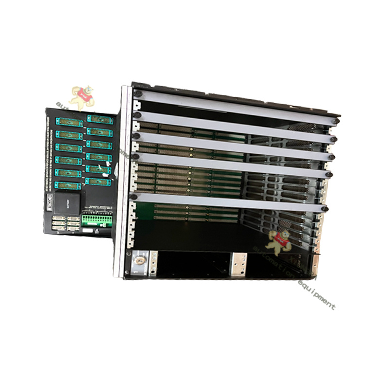
- The panel is connected to the 3604E digital output module via a backplane cable to enable signal transmission and control.
- Power Supply ConnectionConnect a 24 VDC DC power supply to the panel’s PS1 (positive power terminal) and PS2 (negative power terminal) to provide power for the panel and connected loads.
- Load ConnectionEach output point corresponds to one field load interface. The load terminal of the field device must be correctly connected to the load terminal of the panel. Ensure correct polarity during wiring to prevent equipment damage caused by reverse connection.
- Typical Wiring Diagram ReferenceThe wiring of a single output point shall follow the circuit logic of Power Supply → Panel → Module → Load to ensure a complete current loop. For the detailed wiring diagram, refer to Figure 78 (Field Wiring Diagram for 9662-810 and 3604E Module) in the Tricon v9–v10 System Field Terminal Guide.
Application Scenarios
The Triconex 9662-810 is mainly applied in industrial fields relying on the Tricon fault-tolerant control system, including but not limited to:
- Process control and Safety Instrumented Systems (SIS) in the petrochemical industry;
- Generator set control and substation automation systems in the power industry;
- Production line automation control in metallurgy, chemical engineering and other industries;
- Other industrial control scenarios requiring high-reliability digital signal output, load protection and status monitoring.
Customers who purchased this product are also browsing the following products:
TRICONEX 4351A TCM Communication Module
TRICONEX 3721 Analog Input Module
triconex 3624 TMR Digital Output Module
Triconex 3008 Main Processors MP3008


 3005319639