Note; All products on this site are special products, the market price has been fluctuating, the specific customer service offer shall prevail, because the product is a new product, the picture is not a real shot, please confirm with customer service before placing an order model and product, price and other details, the site used, new are for sale, please contact customer service communication. 
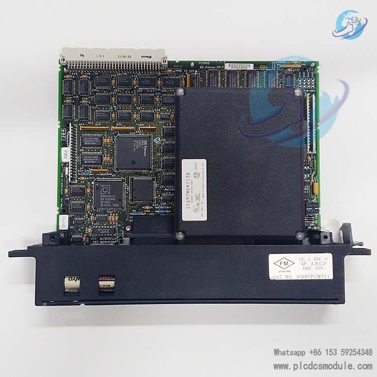
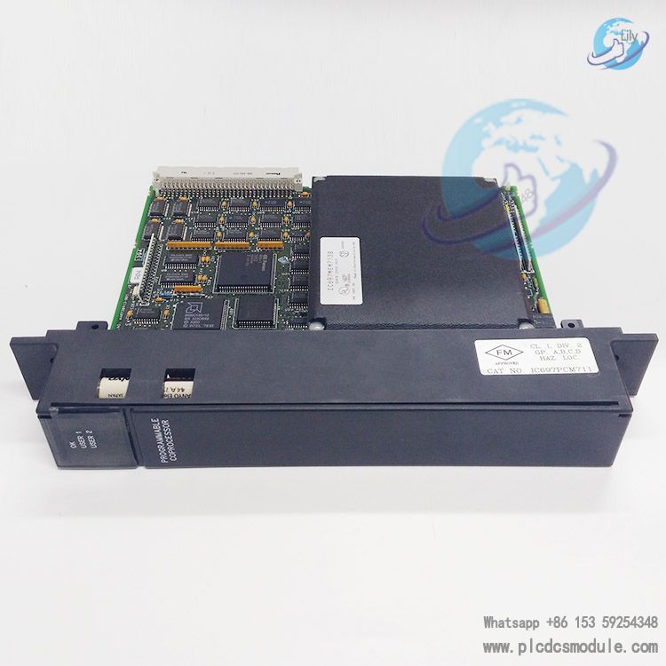
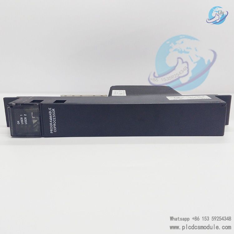
The GE Fanuc IC697PCM711 is a single-slot programmable coprocessor module specifically designed for the Series 90-70 programmable controller system. Centered on a 12MHz 80C186 microprocessor, it delivers performance equivalent to 90% of an IBM AT computer. Boasting features including dual-task processing, flexible communication interfaces, scalable memory capacity and user-friendly software configuration, it serves as a high-efficiency auxiliary processing unit for PLC systems
.
It operates independently without requiring application program support from the PLC central processing unit (CPU). Communicating with the PLC CPU via the backplane, the module can take on critical tasks on its own, such as operator interface management, real-time computing, data storage, data acquisition and data communication. Moreover, a single IC697 PLC system can support multiple units of this module, significantly enhancing the system’s scalability and processing capability.
related documents
 IC697PCM711.pdf
Core Features
Hardware Configuration and Performance
Powered by a 12MHz 80C186 microprocessor, the module comes with a basic configuration of up to 96KB battery-backed CMOS logic and data memory. It supports expanding the program/data memory to 64KB, 128KB, 256KB or 512KB via optional memory expansion boards (IC697MEM713/715/717/719), meeting the requirements of applications with varying levels of complexity. The module features a dip-switch and jumper-free design, and can be fully configured via programming software on MS-DOS or Windows platforms for easy operation.
Dual-task Processing Capability
It supports simultaneous operation of MegaBasic programs and communication interface functions, enabling parallel execution of multiple tasks. This ensures the stable running of custom application programs without compromising the reliability of data communication, thereby improving the comprehensive utilization efficiency of the module.
Communication Interfaces
Equipped with two RS-232/RS-422/RS-485 compatible serial ports (Port 1 and Port 2), the module supports full-duplex data communication at a maximum speed of 9.6Kbaud per port when both ports are in operation simultaneously; the maximum data rate can reach 19.2Kbaud when a single port runs independently, making it suitable for different communication scenarios and device connection requirements. The ports adopt 25-pin connectors, with RS-232 signals compliant with industry standards. Pins not used for RS-232 are allocated to RS-422/RS-485 signals, featuring clear pin definitions to facilitate wiring and debugging.
Real-time Clock and Status Indicators
It has a built-in real-time calendar clock synchronized with the PLC, ensuring the accuracy of time-sensitive data processing. The front panel of the module is fitted with three green status LEDs: the top LED indicates the module’s operating status, while the two bottom LEDs can be assigned to custom configuration functions, providing intuitive feedback on the module’s running conditions. A reset button is also provided: a short press (less than 5 seconds) restarts the application program, and a long press (more than 5 seconds) restores the factory default settings (memory data remains intact, only communication default configurations are reset).
Power Supply and Battery Backup
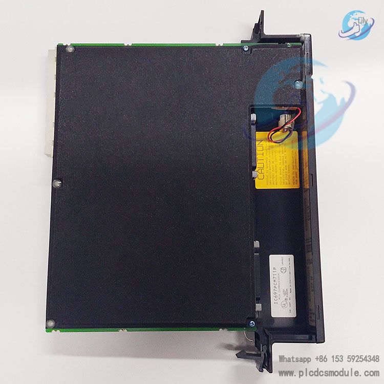
The module draws operating power from the 5V bus of the PLC rack, with a rated operating current of 1.0A. It is equipped with an IC697ACC701 lithium battery to retain user memory data in case of power failure. The battery has a shelf life of 10 years at 20°C (68°F), with a nominal memory data retention time of 6 months without external power supply. To prevent data loss during battery replacement, the new battery must be installed before removing the old one.
Installation Requirements and Procedures
Installation Prerequisites
Before installation, it is mandatory to refer to the relevant programmable controller installation manual (Document Reference 5) to ensure that the installation operations comply with safety and system specifications. The rack power supply must be turned off during installation to prevent equipment damage caused by hot swapping.
Installation Steps
- If memory expansion is required, install the memory expansion board first.
- Connect the lithium battery to any battery interface on the module.
- Install the module into the designated slot of the PLC rack (a typical configuration is Rack 1, refer to Figure 1).
- Turn on the rack power supply. After the module is powered on, the top LED will flash. Upon completion of diagnostics with no faults detected, the top LED will remain steadily lit, indicating a successful installation.
System Connection Specifications
In the PLC system where the module is installed, the total length of all interconnection cables from the Bus Transfer Module (BTM) to the last Bus Receiver Module (BRM) shall not exceed 15 meters (50 feet). The maximum length of the IC66* series I/O bus is 2285 meters (7500 feet). The system supports a maximum of 8 racks, and all racks must be at the same ground potential to ensure stable signal transmission.
Programming and Configuration
Programming Equipment and Software
An IC647/IC640 computer or IBM-compatible PC (XT/AT/PS/2, etc.) with PCM development software installed is required. Connect the programming device to the default top port (3PL) of the module via an IC697CBL705 RS-232 cable, with the default communication baud rate set to 19200 bps.The programming and configuration software is compatible with MS-DOS or Windows systems. It allows users to configure serial port parameters, define the interface with the PLC CPU, select task functions, and write MegaBasic application programs. For detailed operations, refer to the PCM Support Software User Manual (Document Reference 3) and MegaBasic Programming Language Reference Manual (Document Reference 4).
Configuration Features
The module has no user-operable hardware configuration switches. All functional configurations are implemented via software, making the configuration process flexible and error-resistant. Parameters such as the module’s communication mode and task priority can be adjusted according to actual application scenarios.
Application Scenarios and System Compatibility
Application Scenarios
Widely used in the field of industrial automation, it is suitable for PLC systems requiring additional processing capacity, such as real-time data calculation for complex processes, multi-device data acquisition and aggregation, remote device communication networking, and operator interface data interaction. It can reduce the load on the PLC central processing unit and improve the response speed and processing efficiency of the entire control system.
System Compatibility
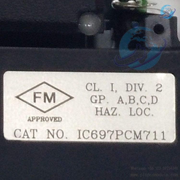
Specifically designed for the GE Fanuc Series 90-70 programmable controller system, it complies with VME Standard C.1. If the system needs to meet standards such as FCC or CE, refer to the Standard Compliance Installation Requirements document attached to the PLC programming software to ensure that the configuration complies with relevant specifications.
Ordering Information
| Part Number | Product Description |
|---|
| IC697PCM711 | 12MHz Programmable Coprocessor Module (20KB base memory, expandable) |
| IC697MEM713 | 64KB CMOS Memory Expansion Board |
| IC697MEM715 | 128KB CMOS Memory Expansion Board |
| IC697MEM717 | 256KB CMOS Memory Expansion Board |
| IC697MEM719 | 512KB CMOS Memory Expansion Board |
| IC697ACC701 | Lithium Battery (for memory backup) |


 3005319639