


With its high surge current capability, flexible configuration mode, clear status indication, and safe mechanical error-proof design, the module is compatible with a wide range of loads including solenoid valves, motor starters, and indicator lights. Widely used in industrial automation control scenarios, it serves as a stable and reliable output interface for connecting PLC systems to external executive devices.
related documents
Features
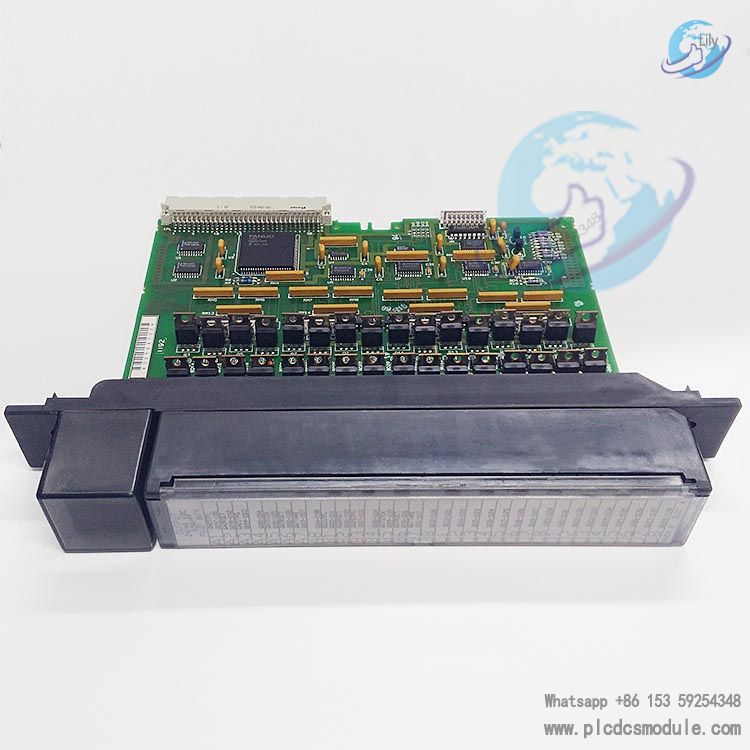
- Output Points & Isolation DesignIt provides 32 output points in total, grouped into 4 independently isolated sets (8 points per set). The isolation performance meets the standards of 1500V insulation between any output point and the backplane and 500V insulation between sets, which can effectively avoid interference between different load circuits and improve system stability.
- Current Carrying CapacityThe long-term rated current per output point is 0.5A, and the maximum total current for each 8-point set is limited to 2A (constrained by the overall heat dissipation capacity of the module). It also features high surge current capacity, with transient surge current reaching 20 times the rated current (i.e., 10A for 20 milliseconds), making it suitable for loads requiring large inrush current during startup (e.g., inductive loads).
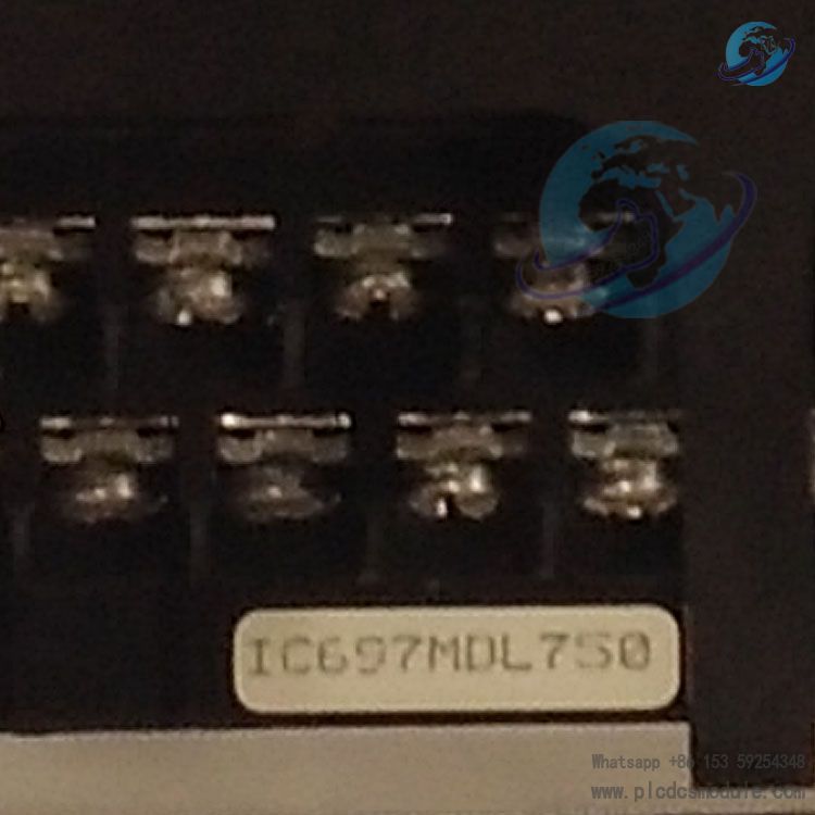
- Status Indication & Mechanical Error ProtectionLED indicators are integrated on the top of the module, which can display the ON-OFF status of each output point on the PLC logic side in real time, facilitating on-site troubleshooting. It is equipped with mechanical keying that can be clamped on the central guide rail of the backplane, ensuring that only modules of the same model can be inserted into the corresponding slot, thus preventing equipment damage caused by incorrect replacement.
- Jumper/DIP Switch-free ConfigurationThe I/O parameters of the module do not need to be set via hardware jumpers or DIP switches. Configuration can be completed via Ethernet TCP/IP or SNP port using programming software running on Windows 95/Windows NT or MS-DOS systems. Supported programming devices include IBM XT, AT, PS/2 and compatible personal computers.
Working Principle & Output Characteristics
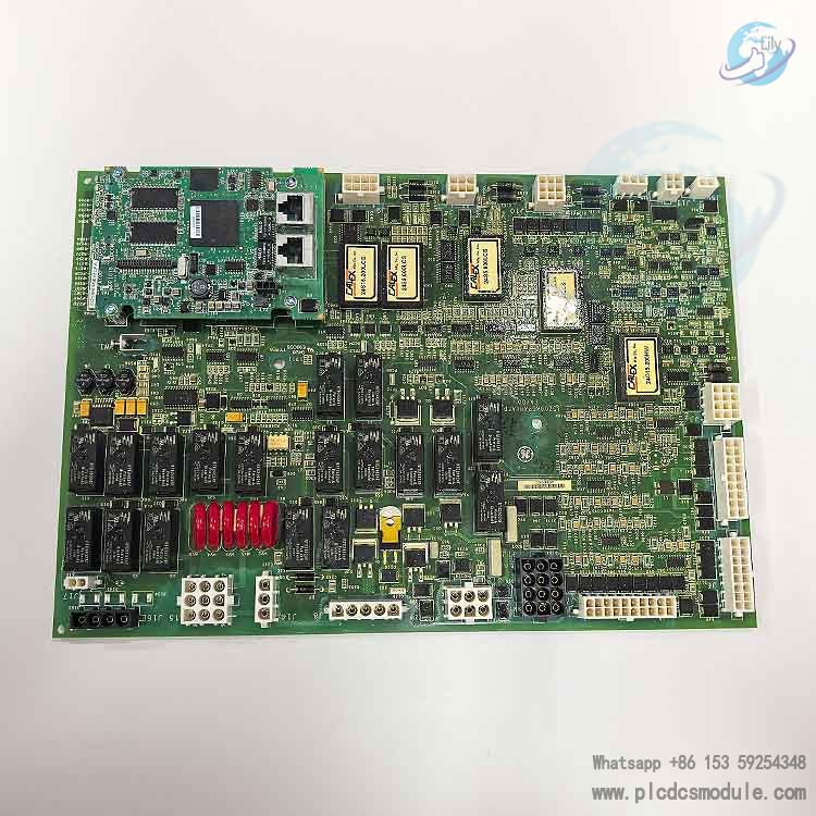
1. Working Principle (Block Diagram)
- Signal Input: The PLC sends logic control signals to the module via the Backplane Interface System.
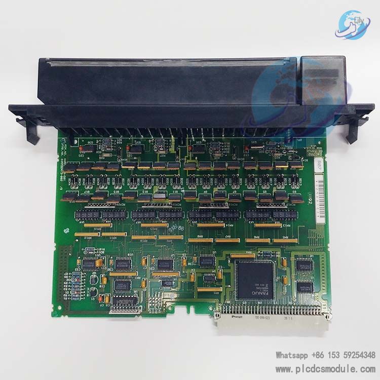
- Isolation Protection: The opto isolator blocks the electrical connection between the module and the backplane, preventing high voltage or interference signals from external loads from reversely entering the PLC system and ensuring the safety of the core controller.
- Drive Output: The output driver converts the isolated signal into actual current and connects to the external field load via the common terminal, realizing on-off control of the load.
- Status Feedback: LED indicators synchronously reflect the logic status of each output point, allowing on-site personnel to intuitively judge the working condition of the module.
2. Output Characteristics
Compatible Load Types: It is suitable for common inductive and resistive loads in industrial scenarios, including solenoids, motor starters, indicators, etc.
Voltage and Current Ranges
Response Time
Technical Specifications and Ordering Information
1. Detailed Technical Specifications (Table 1)
2. Ordering Information (Table 2)
Fault Modes and Protection Design
1. Fault Mode Selection
- Maintain existing output state: When a fault occurs, all output points retain their on/off status prior to the fault. This mode is suitable for critical loads that cannot tolerate sudden shutdowns (e.g., continuous production equipment), preventing production accidents caused by abrupt output changes.
- Turn outputs OFF: When a fault occurs, all output points switch off immediately. This mode applies to safety-critical scenarios requiring emergency shutdown upon faults (e.g., equipment in hazardous areas), reducing accident risks.
2. Fusing
- Littlefuse 312.750: Fast-acting fuse with rated current of 3/4A (0.75A) and rated voltage of 250V
- Bussmann AGC-3/4: Fast-acting fuse with rated current of 3/4A (0.75A) and rated voltage of 250V
Field Wiring and Installation Specifications
1. Field Wiring Requirements
- Independent Power Supply for Isolated Groups: Given that the 4 groups of 8 points are mutually isolated, each group shall be connected to an independent power supply (power terminals of different groups are not interconnected inside the module), ensuring independent operation of loads in each group without mutual interference.
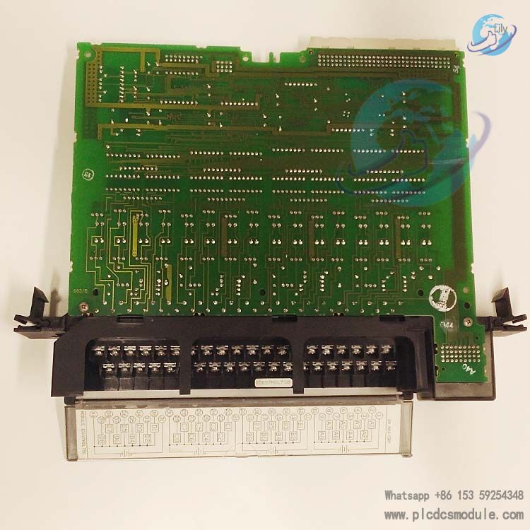
- Terminal Block Specifications: The module is equipped with a removable field wiring terminal block, supporting wire gauges from AWG #22 (0.36mm²) to AWG #14 (2.10mm²). Two wires of the same gauge can be connected to a single terminal. The terminal block cavity can accommodate a maximum of 40 wires of AWG #14 (2.10mm²).
- Wire Securing and Labeling: A cord tie cleat is provided at the bottom right corner of the terminal block, which can be used to secure wire bundles with cable ties and prevent wire loosening. For wires of AWG #14 gauge, wire labels shall be affixed at least 8 inches (203mm) away from the terminals to ensure the module’s hinged door can close properly.
2. Recommended Wiring Procedures
- Power-off Operation: Turn off the system power before disassembling or installing the terminal block to avoid electric shock or equipment damage.
- Terminal Block Removal: Open the module’s hinged door, loosen the jackscrew securing the terminal block counterclockwise, hold the top of the terminal block and swing it outward to remove (do not pull the terminal block via the hinged door to prevent damage to the door structure).
- Wiring and Securing: Connect wires according to design requirements. After completing all module wiring, fasten the wire bundles through the terminal block’s cleat with cable ties. If the wire bundles are too thick, increase the number of cable ties to enhance securing effect.
- Labeling and Ventilation: Insert the wiring information label attached to the module into the slot on the hinged door (the label has notches on the edges; fold the notched areas if insertion is difficult). The color stripes on the outer side of the label enable quick identification of voltage types (blue: low voltage; red: high voltage). Reserve a minimum clearance of 6 inches (152mm) above and below the rack to prevent wire bundles from blocking the rack ventilation holes and ensure module heat dissipation.
3. Module Removing Steps
- Gripping Position: Hold the top and bottom of the module housing with both hands, place thumbs on the front of the housing, and hook fingers onto the plastic buckles on the back of the housing.
- Releasing Buckles: Squeeze the rack buckles on the back with fingers to disengage them from the rack guide rails, and pull the module outward at the same time to separate it from the backplane connector.
- Extracting Module: Slide the module along the rack’s card guide rails until it is completely removed from the rack.
Customers who purchased this product are also browsing the following products:
GE IS210MVRAH2A Mark VI Interface Board
GE DS200SLCCG1ACC Mark V LAN Communications Card
GE IS200VAICH1DAB Mark VI Analog Input/Output Board
GE FANUC MTL 8101-HI-TX PAC8000 8-channel Analog Input module


 3005319639