


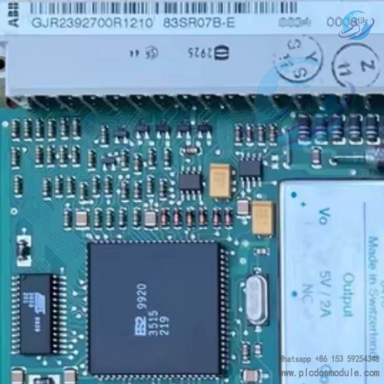
ABB 83SR07‑E/R1210 (Type GJR2392700R1210) is a dedicated 1/2-channel continuous output analog control module for the PROCONTROL P system. It is mainly used for closed-loop control of single/dual-loop process variables, supports actuation of electro-hydraulic, electric, and motor-driven actuators, and features hardware self-monitoring, bumpless redundant switchover, bus diagnostics, and cycle synchronization. It serves as a high-reliability control unit for critical continuous processes in power plants, petrochemical facilities, and other industrial applications.
1. Core Positioning and Applications
- System Affiliation: Analog control component for ABB PROCONTROL P/DCS systems
- Function: Stored-program control for 1–2 process variables with continuous regulating output
- Compatible Actuators: Electro-hydraulic actuators, electric actuators, motor-driven actuators
- Typical Applications: Fossil / nuclear power plant auxiliary control, chemical processes, metallurgical continuous processes, energy station control
- Redundancy Capability: Can form active-standby redundancy with the 88TR01 redundancy control module for uninterrupted switchover
2. Key Functions and Features
2.1 Redundancy Design
- Active-standby parallel processing with synchronous messages ensuring bumpless switchover within ≤10ms
- Both active and standby units perform self-monitoring; faults are reported to the 88TR01 redundancy control module via SSG
- Process interface X21 uses parallel wiring; the online unit connects load resistors while the standby unit is disconnected
- The standby unit periodically sends heartbeat messages for bus diagnostics
- Automatic synchronization after restart; the ST LED illuminates and a synchronization monitoring response is triggered until synchronization is complete
2.2 Control and Calculation
- Supports continuous PID and other function blocks; function blocks with memory are synchronized from the online unit to the standby unit
- Control cycle: 100ms for single loop, 200ms for dual loops
- Dual hardware process interfaces for field signal connection and actuator driving
- Can integrate advanced main control logic to implement complex regulation strategies
2.3 Diagnostics and Monitoring
- Full hardware / software self-test: parameters, channels, processing, bus, checksum, timers, etc.
- Faults reported via SST; front-panel ST/SG LEDs provide visual indication
- 246-bit diagnostic register maps fault types, supporting localization via the CDS diagnostic system
- Checksums generated for EEPROM/RAM and firmware to ensure consistent active-standby configuration
2.4 Configuration and Engineering
- No special configuration required for redundancy; only identical structure, address, parameters, and limit lists for active and standby units
- Jumpers X200/X201/X202/X203 must be set identically on active and standby units
- Configuration, simulation, verification, and consistency checks performed via the PDDS tool
- Supports online simulation with consistent simulation signals for redundant channels
3. Interfaces and Electrical Specifications
- Bus Interface: X11 (station bus + operating voltage USA/USB)
- Process I/O: X21 (full-range analog input / continuous regulating output)
- Operating Voltage: +24V DC
- Power Consumption: 2.3–3.5W in online mode (varies with voltage and configuration)
- Output Enable / Disable Time: Both ≤10ms
- Mounting: Rack-mounted, compatible with standard PROCONTROL cabinets
4. Technical Data Summary
| Item | Specification |
|---|---|
| Control Loops | 1/2-channel continuous analog |
| Control Cycle | 100ms (single loop) / 200ms (dual loops) |
| Redundant Switchover | Bumpless, ≤10ms |
| Operating Voltage | +24V DC |
| Power Consumption | 2.3–3.5W online |
| Communication | Station bus, heartbeat / synchronization messages |
| Diagnostics | CDS + panel LEDs + diagnostic registers |
| Address Range | 0–58 |

Frequently Asked Questions (FAQ)
Q1: How does the module achieve bumpless redundant switchover?A: The active and standby units operate in parallel. The online unit synchronizes status and memory data in real time via synchronization messages. Upon a fault, the redundancy control module 88TR01 initiates switchover while maintaining continuous process output, with a switchover time ≤10ms and no shock or disturbance.
Q2: What do the illuminated ST/SG LEDs on the panel indicate?A:
- ST LED: Module fault / initialization / incomplete synchronization; reported via SST, corresponding to static / dynamic alarms in the diagnostic register
- SG LED: SSG line activated; the redundancy module has detected a fault on this module. Check hardware, firmware, channels, and bus connections.
Q3: What happens if active and standby module configurations are inconsistent?A: Inconsistencies in structure, address, parameters, limit lists, or jumpers will cause synchronization failure, checksum errors, loss of redundancy, and abnormal switchover. Full consistency must be ensured via PDDS with checksum verification.
Q4: Is it normal to receive “synchro-monitoring responded” after restart?A: Yes. After restarting and entering operation mode, the standby unit triggers this alarm until all synchronization messages are received. The alarm clears automatically once full synchronization is achieved, and redundancy can only be enabled when active and standby statuses are consistent.
Q5: What types of actuators does the module support?A: It supports electro-hydraulic actuators, electric actuators, and motor-driven actuators. It can perform local positioning or continuous regulation via power electronic systems, compatible with mainstream industrial regulating mechanisms.
Q6: How to quickly troubleshoot bus communication faults?A:
- Verify the address is within the valid range 0–58
- Check hardware fault bits of the bus adapter
- Confirm the transmitter is not disabled by the bus module
- Verify checksums and reload the configuration list
- Inspect X11 bus and power supply connections
Q7: What are the key wiring rules for a redundant group?A:
- All X21 process terminals of the same redundant pair are connected in parallel
- Jumpers X200–X203 are set identically on active and standby units
- Load, output, and power are automatically disconnected on the standby unit; only the online unit drives the load
- Synchronization messages are processed automatically by the system with no additional configuration required


 3005319639