


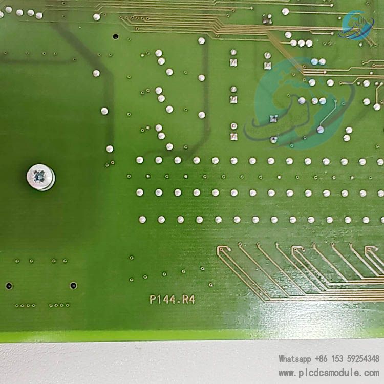
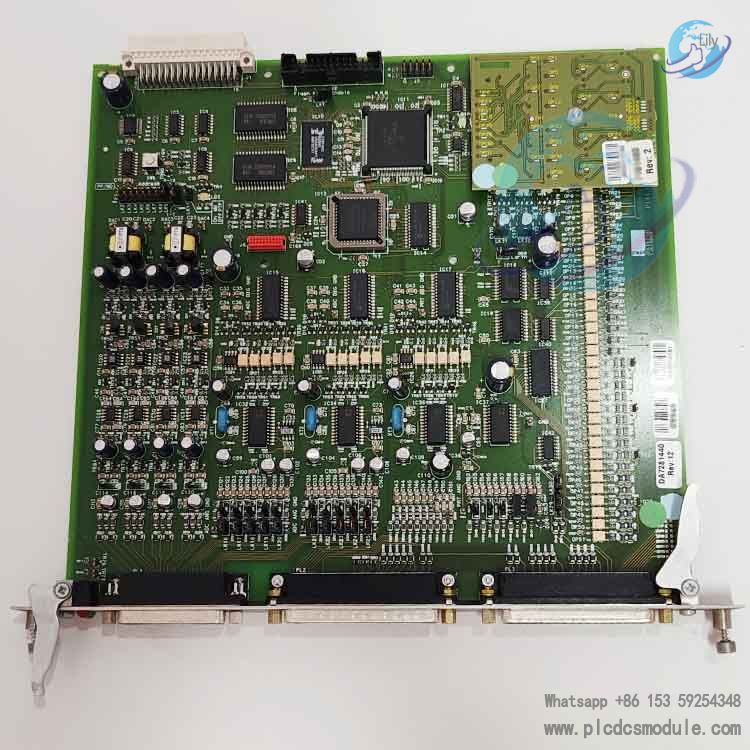
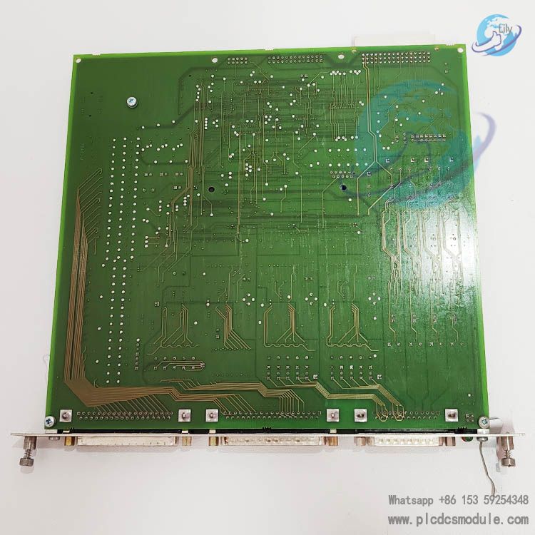
EMERSON P144.R4 is a standard I/O module designed by Emerson specifically for the FloBoss S600+ flow computer. It integrates versatile signal processing capabilities, including digital input/output, analog, pulse, frequency, and RTD signals. Featuring a modular plug-in structure and backplane wiring design, it is suitable for custody transfer and process metering applications in the oil & gas and chemical industries.
It fulfills integrated I/O requirements such as field status acquisition, control of valves, pumps and other equipment, flow pulse counting, and density & temperature measurement, serving as the core hardware component for field signal access and control output in the S600+ system.
Core Positioning & Hardware Foundation
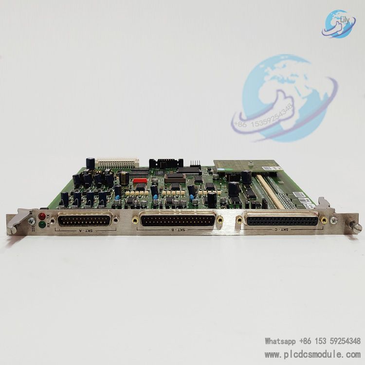
The P144.R4 is a standard I/O module for the FloBoss S600+ flow computer, supporting panel-mounted chassis expansion.A single host can be equipped with up to 3 P144 modules, which connect to field wiring via the backplane SKT‑A/SKT‑B/SKT‑C interfaces.All modules require address configuration via DIP switches (Address 1 for the first module, Address 2 for the second, Address 3 for the third) to ensure stable system identification and communication.
Digital Input (DI) Specifications
- Number of Channels: 16 optically isolated digital input channels
- Grouping: 4 groups × 4 single-ended inputs, with a common terminal for each group
- Electrical Characteristics: Compatible with 24V DC field signals; maximum input 100mA @ 24V DC
- Isolation: Optical isolation between channels for improved noise immunity and field safety
- Applications: Dry contact / active status acquisition for valve position feedback, pump status, limit switches, alarm contacts, etc.
Digital Output (DO) Specifications
- Number of Channels: 12 open-collector digital output channels
- Drive Capacity: Maximum load 100mA @ 24V DC, suitable for solenoid valves, indicators, relay coils and other field actuators
- Output Type: Contactless open-collector structure, fast response, long service life
- Applications: Discrete control for valve actuation, pump start/stop, alarm output, interlock protection, etc.
Additional I/O Capabilities (Complementary to Digital Signals)
Beyond digital signals, the P144.R4 integrates multiple interface types for flow metering applications:
- Analog Input: 12 channels; 10 channels configurable for 0‑5.25V / 0‑22mA, 2 channels dedicated to 0‑22mA; dual independent floating-point A/D conversion
- Analog Output: 4 channels with floating-point D/A conversion, maximum load 650Ω, supporting sourcing / sinking wiring
- Pulse Input: 4 channels (requires P148 turbine interposer board), range 1Hz‑10kHz, supporting dual-pulse verification and integrity checking
- Pulse Output: 5 programmable channels for electronic counters, sampler control, and flowmeter calibration simulation
- Frequency Input: 3 channels, 0‑10kHz, AC/DC coupling selectable, suitable for density transmitter signals
- RTD Input: 3 channels, supporting Class A 4-wire PRT, temperature range ‑100℃ ~ +200℃, compatible with DIN / American standard curves
Scan Timing & Accuracy Specifications
- 1 P144 module: Sampling rate 2Hz, real-time refresh of DI/DO
- 2 P144 modules: Sampling rate 1Hz, synchronized DI/DO refresh without data loss
- 3 P144 modules: Sampling rate 1Hz, supporting multi-loop expansion
- Calibration Standard: Calibration required if analog input error > 0.02% or output error > 0.1% to ensure metering accuracy
Electrical & Installation Specifications
- Power Supply: Powered by 24V DC (20‑32V DC range) from the S600+ host P152 CPU board; on-board isolated 15V/24V loop power supplies
- Wiring: Backplane D-sub connectors, grouped wiring for digital channels to simplify field cabling
Protection: Industrial-grade design, suitable for high-interference oil and gas field environments, supporting panel mounting and fixation.
Frequently Asked Questions
- Does the P144.R4 digital input support dry contacts or active signals?It supports both dry contacts and 24V DC active signals. With 16 optically isolated input channels and a maximum input of 100mA @ 24V DC, it is compatible with mainstream field signals such as valve position feedback and limit switches.
- How to troubleshoot when the digital output fails to drive a solenoid valve?First confirm the load current is ≤ 100mA and the voltage is 24V DC. Check that the open‑collector output wiring is correct with no reverse voltage. Verify stable power supply from the host and no voltage drop caused by overload.
- How to set addresses for multiple P144 modules?Addresses are set via on‑board DIP switches: Address 1 for the first module, Address 2 for the second, and Address 3 for the third. When used with a P154 check module, addresses are assigned sequentially to avoid conflicts that prevent system recognition.
- How to resolve heavy interference and false toggling of digital signals?Use shielded cables and route them away from power cables. Utilize channel optical isolation and single‑point grounding to reduce common‑mode interference. Check that field grounding is proper to avoid ground loop interference.
- How to locate a faulty digital channel on the P144.R4?View channel status through the S600+ configuration software. Test DI channels individually by shorting or opening the circuit. Measure DO output levels to verify drive capability and ensure no overload or loose wiring exists.
- Can digital, pulse, and analog channels be used simultaneously?Yes. As an integrated I/O board, the P144.R4 allows digital, analog, pulse, frequency, and RTD channels to operate independently without mutual interference, meeting requirements for multi‑signal acquisition and control.


 3005319639