


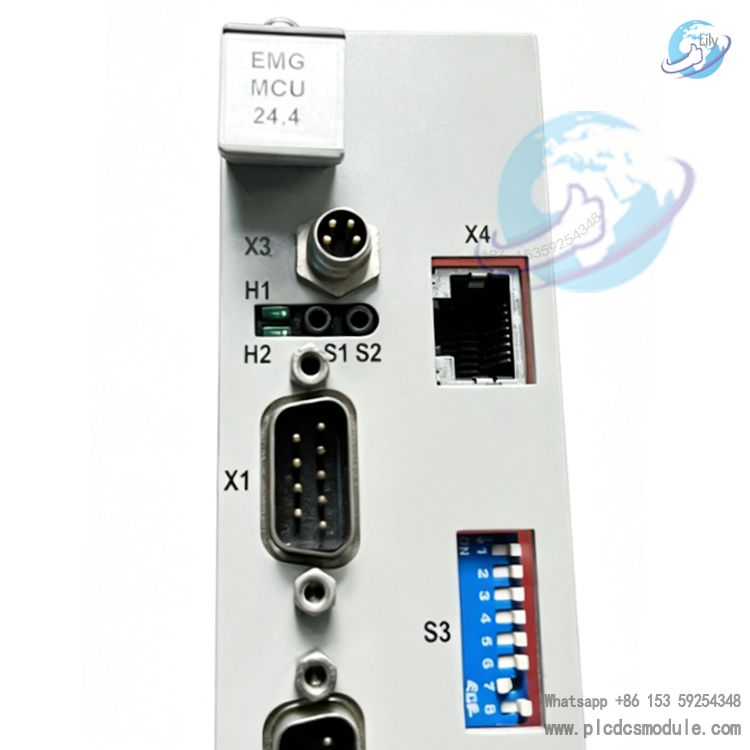
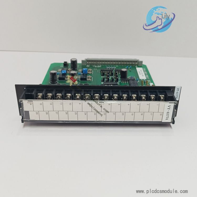
The EMG MCU 24.4 is a PLC control motherboard specially developed by Germany-based EMG for industrial electric actuators. As a core component of the EMG actuator control system, it integrates an MCU main control unit, I/O interfaces, communication circuits and a power management module. It is designed to realize actuator functions including position control, torque protection, travel limit and bus communication. It is widely applied in the driving and control of valves and dampers in industries such as electric power, metallurgy and water treatment.
Core Hardware Specifications
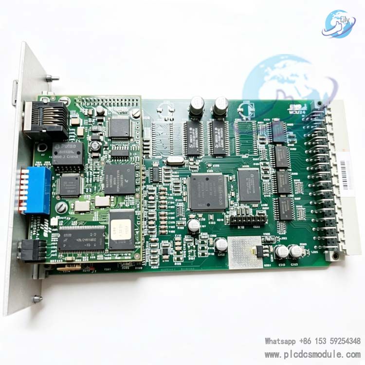
1. Main Control Unit
Processor: Industrial-grade 32-bit ARM Cortex‑M4 core MCU with a main frequency of 40 MHz. It integrates an FPU floating-point operation unit and supports real-time control algorithms.
Storage Configuration:
- Program Flash: 512KB (for storing control programs and parameters)
- Data RAM: 64KB (real-time data caching)
- EEPROM: 8KB (retains key parameters after power failure, such as limit values and torque thresholds)
2. Power Supply System
Operating Voltage: DC 24V (±20%, compatible with standard industrial power supply)Power Consumption: Static power ≤ 10W; full-load power ≤ 15W. Equipped with overvoltage, reverse connection and surge protection functions.Onboard Output Power: DC 24V/500mA, providing power for sensors and encoders.
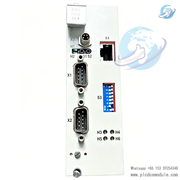
3. I/O Interfaces
- Digital Input (DI): 12 channels, DC 24V compatible, supporting sourcing/sinking wiring. Includes 4 high-speed inputs (response time ≤ 2μs) for signal collection of limit switches, torque switches and remote start-stop commands.
- Digital Output (DO): 8 channels, PNP transistor output. Each channel carries DC 24V/0.5A load; 4 high-speed outputs (PTO pulse output, up to 100kHz) for controlling motor forward/reverse rotation, braking and fault alarm.
- Analog Input (AI): 2 channels, selectable 0–10V/4–20mA, used for valve position feedback and torque sensor signal acquisition, with an accuracy of ±0.1% FS.
- Analog Output (AO): 1 channel, 4–20mA, transmitting valve opening signals to the DCS system.
4. Communication Interfaces
- CAN Bus: 1 channel, CAN 2.0A/B, baud rate: 125k–1Mbps. Compatible with EMG dedicated protocol and Modbus-CAN, capable of connecting to host computers, HMI touch screens or multi-device networking.
- RS‑485: 1 channel, supporting Modbus-RTU, baud rate: 9.6k–115.2kbps, for communication with third-party PLCs.
- Debug Interface: 1 RS‑232 port for program downloading, parameter configuration and on-site debugging.
5. Mechanical & Environmental Parameters
- Dimensions: 160mm × 120mm × 30mm, applicable for standard DIN rail mounting or bolt fixing.
- Operating Temperature: −20℃ ~ +60℃, industrial wide-temperature design for harsh working conditions.
- Ingress Protection: IP20 (circuit board), dustproof and splashproof, to be installed inside control cabinets.
- Vibration Resistance: 10–50Hz, 2g on X/Y/Z axes, compliant with industrial equipment vibration standards.
Core Functions
- Actuator Closed-loop ControlSupports position closed-loop (encoder feedback) and torque closed-loop (sensor feedback) to realize precise positioning and overload protection.
- Stroke and Torque ProtectionBuilt-in dual protection of soft limit and hard limit. Torque thresholds for opening and closing directions are configurable. The unit will stop automatically and trigger an alarm in case of overload.
- Local / Remote Control SwitchingSeamless switching between local manual operation (buttons / handwheel) and remote control (DCS / PLC signals) without disturbance.Fault Diagnosis and AlarmReal-time monitoring of power supply status, motor overheating, communication errors and limit faults. Alarms are indicated via LED indicators and dry contact output, with historical fault record query supported.Parameter ConfigurationLimits, torque, speed and communication parameters can be set via configuration software or local panel. Parameter backup and restoration functions are available.
Application Scenarios
- Power Industry: Electric actuation and control of boiler flue gas dampers, desulfurization and denitrification valves, and feed water valves.
- Metallurgical Industry: Drive control of blast furnace cold air valves, hot blast valves and rolling mill baffles.
- Water Treatment: Actuation control for aeration valves, drain valves and grid machines in sewage treatment plants.Petrochemical Industry: Remote automatic control of pipeline valves and tank inlet/outlet valves.
Frequently Asked Questions
Q1: Which EMG actuator models are compatible with MCU 24.4?A1: It is applicable to EMG DREHMO series electric actuators, including DIM, DEM and EM series, covering on-off and modulating actuators with a torque range of 50–5000Nm.
Q2: How to complete program downloading and parameter configuration?A2: Use the dedicated EMG debugging software (EMG Config Tool) and connect to a PC via the RS‑232 interface to realize program upload and download, parameter modification, real-time monitoring and fault diagnosis. Key parameters can also be directly configured on-site through the local actuator panel with display.
Q3: How to troubleshoot communication errors of CAN / RS‑485?A3:
- Wiring inspection: Check whether CAN bus H/L lines and RS‑485 A/B lines are reversely connected, and confirm that 120Ω terminal resistors are correctly installed at both ends of the bus.
- Parameter verification: Ensure the baud rate, address and protocol type (Modbus‑RTU / CAN) are consistent with the master station.
- Hardware inspection: Measure interface voltage (CAN‑H≈3.5V, CAN‑L≈1.5V; RS‑485 A−B≈2–6V) to rule out short circuits or open circuits.
Q4: What solutions for the “torque overload” fault during actuator operation?A4:
- Mechanical load inspection: Check the valve or damper for jamming and foreign blockage; manually crank the equipment to confirm mechanical flexibility.
- Torque parameter adjustment: Appropriately increase the torque threshold for opening and closing directions in the debugging software (within the equipment rated range).
- Sensor inspection: Check for loose or damaged wiring of the torque sensor, and calibrate the zero point and range of the sensor.
Q5: How does MCU 24.4 communicate with third-party PLCs (Siemens, Mitsubishi, etc.)?A5: Two communication methods are supported:
- Modbus‑RTU (RS‑485): The third-party PLC acts as the master station, while MCU 24.4 works as the slave station to read and write I/O status, valve position data and fault information.
- Modbus‑CAN: Adopt CAN bus networking, suitable for long-distance and multi-device communication, with both sides required to support the Modbus‑CAN protocol.


 3005319639