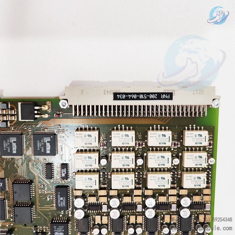
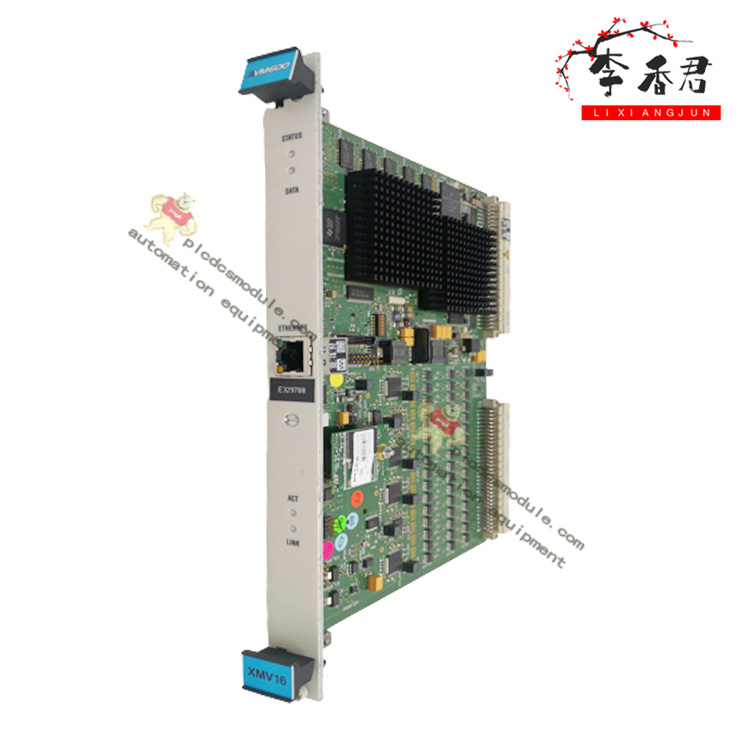
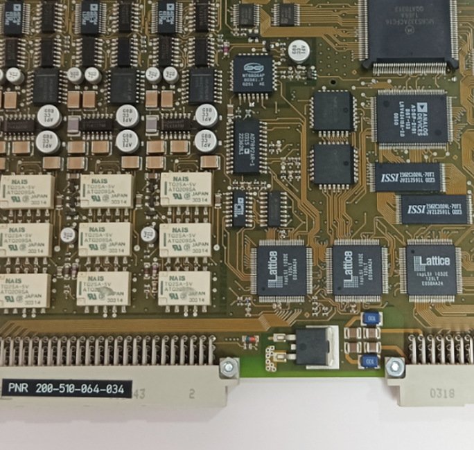
The Vibro-Meter VM600 MPC4 200-510-071-113 is a four-channel machinery protection card manufactured by Vibro-Meter, a brand under Meggitt. As a core component of the VM600 modular monitoring system, it delivers real-time protection and condition monitoring for critical rotating machinery. Compliant with API 670 standards, it is widely used in petrochemical, power, metallurgical and other industries.
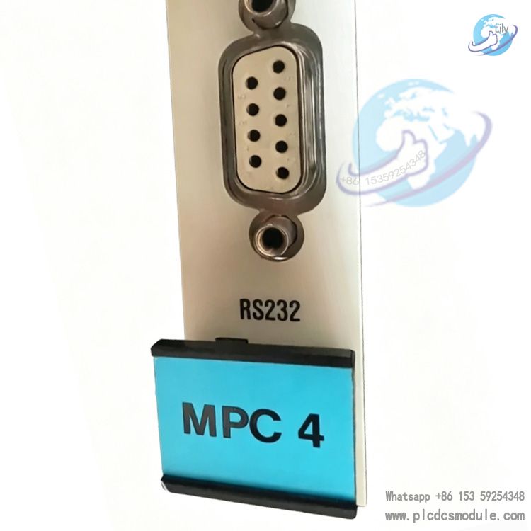
Product Advantages
Highly Reliable Protection, Millisecond TrippingOperates independently of the DCS with hard-isolated protection logic; triggers relay tripping within ≤10ms on excessive vibration, preventing catastrophic equipment damage.
SIL‑Rated Safety and RedundancyThe standard version (200‑510‑071‑113) meets general industrial requirements; an SIL2‑certified version (200‑510‑111‑034) is also available, supporting 1oo2/2oo3 redundancy in compliance with functional safety standards.
High Precision and Strong Anti‑Interference4 dynamic channels + 2 speed channels, frequency range 0.1Hz–10kHz, accuracy ±0.5%, resolution 0.01Hz;Onboard FPGA+DSP for real‑time filtering and spectrum analysis, suppressing electromagnetic interference.
Hot‑Swap Capability and Easy MaintenanceSupports module replacement without shutdown, cutting maintenance time by 70%; built‑in BIST self‑diagnostics enables remote monitoring of module health status.
All‑in‑One Integration, Simplified SystemSingle card integrates signal acquisition, processing, alarming, tripping and communication; pairing MPC4 + IOC4T forms a complete protection subsystem.
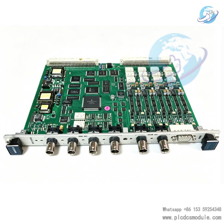
Product Features
Channel Configuration: 4 dynamic inputs (acceleration/velocity/displacement/pressure), 2 speed/phase inputs (TTL/magnetoelectric).
Signal Processing: Programmable high‑pass/low‑pass/band‑pass/notch filters; peak/RMS/phase monitoring; FFT spectrum and envelope analysis.
Alarming and Tripping: Two‑level alarm (Alert/Danger) + overspeed protection; 8 safety relay outputs with customizable logic.
Communication Interfaces: Modbus RTU/TCP, RS‑485, Ethernet; 4–20mA analog output for seamless integration with DCS/PLC.
Environmental Adaptability: Operating temperature ‑20°C~+70°C (extended: ‑40°C~+85°C); resistant to vibration, salt spray and electromagnetic interference.
Dimensions & Weight: Standard 19‑inch, 1U height; approx. 0.4kg, compatible with ABE04x racks.
Application Scenarios
Power Industry: Shaft vibration/shaft displacement/overspeed protection for steam turbine generator sets, gas turbines and boiler feedwater turbines.
Petrochemical Industry: Vibration monitoring for cracking gas compressors, synthesis gas compressors, LNG refrigerant compressors and main catalytic blowers.
Metallurgical Industry: Condition monitoring and fault early warning for blast furnace blowers, TRT power recovery turbines and large motors.
Industrial Turbines: Online protection for high‑speed rotating machinery such as large fans, pumps and centrifuges.
Related / Supporting Products
IOC4T I/O Card: Paired with MPC4, provides relay outputs, sensor power supply and buffered signal outputs.
CPUMMk2 Communication Card: Rack master controller with redundant communication, connecting to DCS/PLC/host system.
RDC8U/RPS6U Relay Modules: Expand safety relay outputs for multi‑device interlocking protection.
VM600 MPSx Software: Configuration, parameter setting, data logging, trend analysis and fault diagnosis.
Sensors: Eddy current displacement sensors, piezoelectric acceleration sensors, magnetoelectric speed sensors.
Installation & Maintenance
1. Installation Steps
- Rack Mounting: Install in a standard 19‑inch ABE04x rack, secure in a single slot and ensure proper grounding.
- Module Pairing: Install MPC4 in front and IOC4T behind, connect via backplane bus and tighten slot screws.
- Sensor Wiring: Dynamic signals to BNC connectors, speed signals to terminal blocks; shield grounding at the module side only to avoid ground loops.
- Power & Communication: Connect to 24V DC or rack redundant power; connect Ethernet/RS‑485 to host/PLC.
- Software Configuration: Set channel parameters, filters, alarm thresholds and tripping logic via MPSx, then download configuration.
2. Routine Maintenance
Regular Inspection
- Module indicators: PWR (Power), RUN (Operation), ALM (Alarm), TRIP (Trip) status normal.
- Terminals: No looseness or oxidation, shielding intact.
- Sensors: Clean, no oil contamination, installation gaps within specification (e.g., ~1mm for eddy current probes).
Calibration
- Channel accuracy: Input standard signals to verify amplitude/phase errors.
- Alarm/trip test: Simulate over‑limit signals to validate relay action and interlock logic.
Firmware Upgrade: Update firmware regularly via MPSx to fix vulnerabilities and optimize performance.
FAQ
Q1: What is the difference between MPC4 and MPC4Mk2? Are they compatible?A1: MPC4 is the classic model (discontinued in 2027, spare parts available until 2027); MPC4Mk2 is the upgraded version with enhanced functions and IEC 62443 cybersecurity support. Hardware is not directly compatible; requires matching IOC4Mk2 and VM600Mk2 racks.
Q2: Module alarms but no equipment abnormality — how to troubleshoot?A2: Prioritize interference and wiring checks:
- Damaged sensor cables or poor shield grounding → Rewire, single‑end grounding.
- Improper filter parameters → Enable adaptive filtering, adjust bandwidth.
- Power supply fluctuations → Check redundant power, add voltage regulators.
- Severe external EMI → Keep away from inverters/large motors, use shielded conduits.
Q3: Is hot‑swap safe? Will data be lost?A3: Hot‑swap is supported and designed for non‑stop replacement. During replacement:
- The module goes offline automatically; protection logic is maintained by IOC4T without interruption.
- Transient data is cached and synced automatically upon reinsertion; no critical data loss.
- It is recommended to disable the channel in software first before physical removal for lower risk.
Q4: How to communicate with DCS? What protocols are supported?A4: Supports Modbus RTU (RS‑485)/TCP (Ethernet) by default for reading vibration/speed/alarm/trip status; 4–20mA analog output connects to DCS analog modules for hard‑wired redundancy.
Q5: What is the difference between the SIL2 version (200‑510‑111‑034) and the standard version?A5: The SIL2 version complies with IEC 61508 SIL2 functional safety, featuring redundant architecture and higher fault diagnostic coverage for high‑risk applications (e.g., gas turbines, compressors). The standard version is for general industrial use without SIL certification and is lower‑cost.