


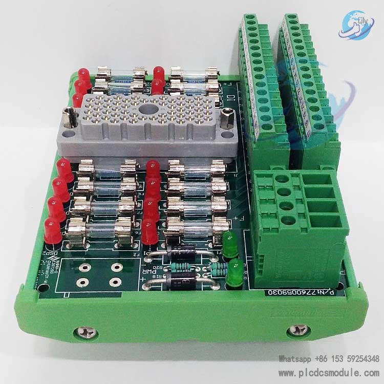
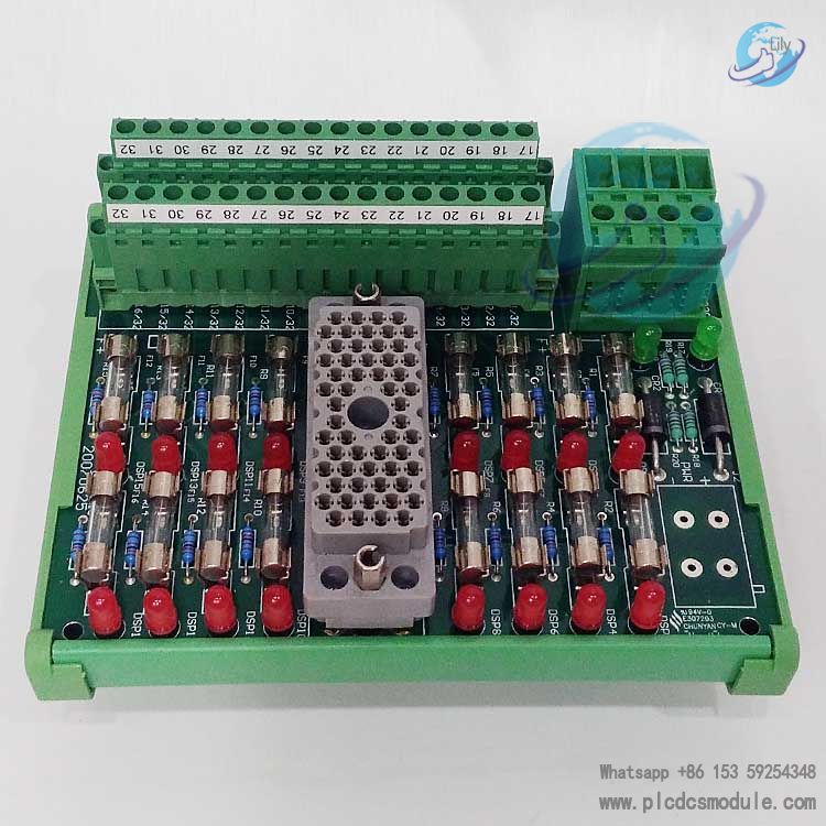
Adopting a commoned structure, the panel comes equipped with 16 input terminals as well as common power terminals (PWR+ and PWR–). Each input point is fitted with a fuse and a blown-fuse indicator, which provides reliable circuit protection and visual monitoring of fault status for the connected digital input modules. Widely suited to the requirements of stable signal transmission and safety protection for digital signal input in industrial control scenarios, it serves as a critical interface component linking the Tricon system to field digital input devices.
related documents
Specifications
Compatible Modules
Core Functions & Design Highlights
- Dual Safety ProtectionEach input point is independently equipped with a fuse, which effectively protects the module and panel from damage caused by faults such as overload and short circuit. Combined with a blown-fuse indicator, it enables intuitive identification of fault points, significantly shortening maintenance and troubleshooting time.
- Commoned Power Supply DesignThe panel adopts PWR+ and PWR– commoned power terminals, which simplify the wiring process and reduce circuit complexity. Meanwhile, it ensures stable and consistent power supply for 16 input points, enhancing the reliability of signal transmission.
- Precise CompatibilitySpecifically designed for digital input modules with a voltage rating of 24 VAC/VDC, it forms an optimal compatibility combination with the 3503E and 3505E modules. This prevents signal distortion or equipment failure caused by voltage mismatch or compatibility issues.
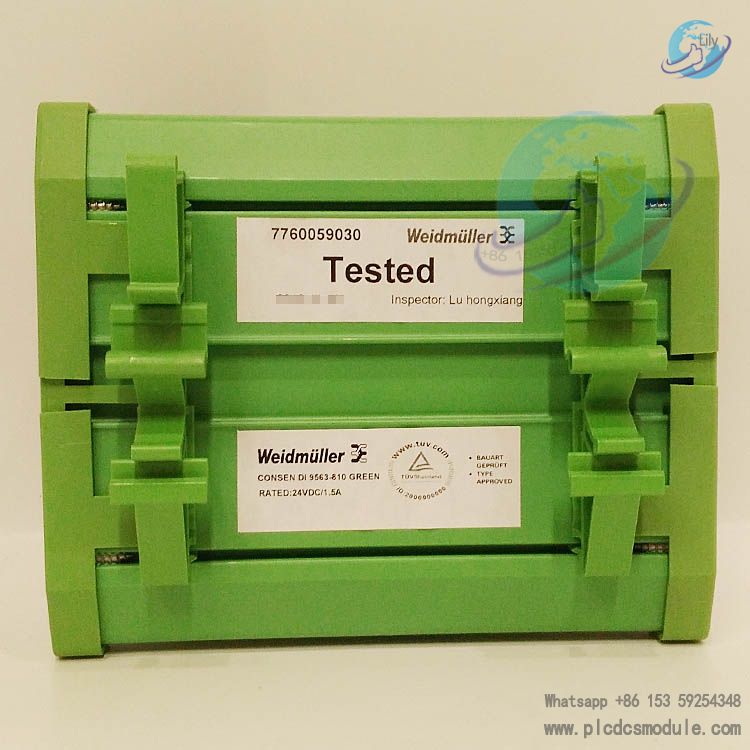
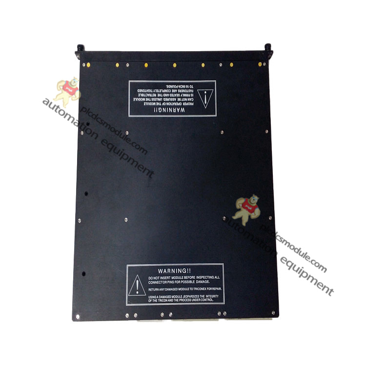
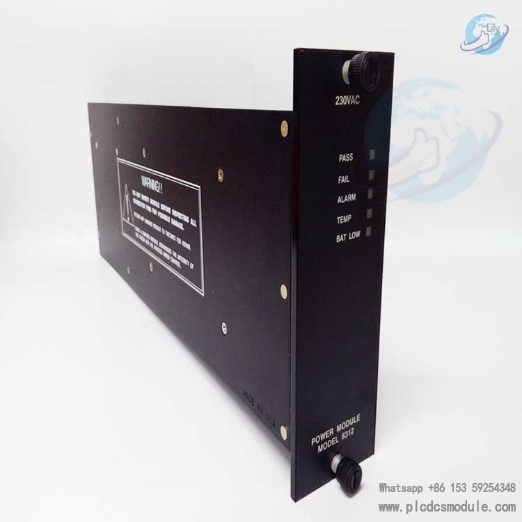
- Industrial-grade Environmental AdaptabilityCompliant with the industrial-grade design standards of the Tricon system, the panel features a DIN rail-compatible plastic housing. It can withstand vibration and electromagnetic interference in harsh industrial environments, ensuring long-term stable operation.
- Flexible Label ConfigurationEquipped with two sets of labels (1–16 and 17–32), it is suitable for the dual-panel combined application scenario with 32-point modules. For detailed instructions on label pasting methods, refer to Appendix F of the document.
Field Wiring Guide
- The panel is connected to the 3503E or 3505E module via a backplane cable to enable signal transmission.
- Power ConnectionConnect a 24 VAC or 24 VDC power supply to the panel’s PWR+ (positive terminal) and PWR– (negative terminal) respectively to provide power for the panel and input circuits.
- Load ConnectionConnect the signal output terminals of field digital input devices to the 16 input terminals of the panel. Ensure correct polarity during wiring to avoid affecting signal acquisition due to reverse connection.
- Redundant ConfigurationWhen used with a 32-point module, two 9563-810 panels must be installed simultaneously, corresponding to points 1–16 and points 17–32 of the module respectively, and the terminal numbers shall be distinguished with matching labels.
- Typical Wiring LogicFollow the circuit architecture of Field Device → Panel Input Terminal → Panel Power Terminal → Module → System to ensure a complete current loop. For details, refer to Figure 8 (Field Wiring Diagram for 9563-810 and 3503E/3505E Modules) in the Tricon v9–v10 System Field Terminal Guide.
Application Scenarios
- Signal acquisition of Safety Instrumented Systems (SIS) and process control equipment in the petrochemical industry;
- Digital input in generator set condition monitoring and substation automation control in the power industry;
- Sensor signal access in production lines of metallurgy, building materials and other industries (such as limit switches and proximity switches);
- Other industrial control scenarios requiring protection, isolation and stable transmission of digital input signals.
Customers who purchased this product are also browsing the following products:
TRICONEX 4351A TCM Communication Module
TRICONEX 3721 Analog Input Module
triconex 3624 TMR Digital Output Module
Triconex 3008 Main Processors MP3008
Triconex HCU3700/3703E | Analog Input FTA with HART Interface module


 3005319639