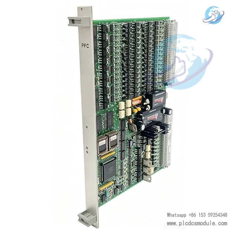
The METSO PDP401 Distributed Processing Unit module (also known as maxDPU4F) is the hardware core of the maxDNA distributed control system. It runs on the Windows CE.net real-time operating system and is a rack-mounted device that occupies a single slot. It can work in combination with IOP input/output modules and communicate with other devices. It is capable of performing functions such as data acquisition, control, and data processing, including comprehensive alarm and calculation, sequence of events data recording, and trend information collection. It features multi-speed processing capability, supports the execution of a large number of control objects, has a fully self-describing object-oriented database and software backplane compatibility, and can be configured for redundant operation, making it suitable for industrial process control scenarios.
Mail: plcdcsmodule@foxmail.com
Phone/Wechat/Whatsapp:+86 15359254348
Note; All products on this site are special products, the market price has been fluctuating, the specific customer service offer shall prevail, because the product is a new product, the picture is not a real shot, please confirm with customer service before placing an order model and product, price and other details, the site used, new are for sale, please contact customer service communication.
The METSO PDP401 Distributed Processing Unit (DPU, also known as maxDPU4F) is the hardware processing core of the maxDNA distributed control system, running on the Windows CE.net real-time multitasking operating system. The PDP401 is a microprocessor-based independent rack-mounted unit that occupies a single slot through an 8-wide maxPAC backplane in the Remote Processing Unit cabinet. It mainly performs core functions such as data acquisition, control, and data processing. It can operate in combination with user-defined maxDNA model IOP input/output modules and can communicate with other devices such as programmable logic controllers and remote terminal units. As a site on maxNET, this DPU scans and processes information for use by other devices in the maxDNA system.
Comprehensive Alarm and Calculation: It can monitor various parameters in the system, issue alarms when parameters exceed the set range, and perform related calculation processing.
Sequence of Events (SOE) Data Recording: Equipped with a built-in SOE recorder, it can monitor up to 512 discrete inputs, scan 1000 times per second. Status changes are time-stamped with a resolution of 1 millisecond and stored in the DPU's 10,000-event buffer. Each input has a separately configured digital filter for contact debouncing.
Trend Information Collection: Continuously collects various trend data during system operation to provide a basis for system analysis and optimization.
Continuous Scanning of IOP I/O Modules: Uninterrupted scanning of Model IOP I/O modules ensures timely acquisition of input and output data.
Execution of Control Algorithms: Executes predefined algorithms (called function blocks) for process control and data acquisition, supporting up to 8500 control objects (function blocks). Function blocks can be combined to create standard and custom block libraries, and they can be as small as atomic blocks (such as AND gates or OR gates).
Hardware Composition and Performance
Control Processor
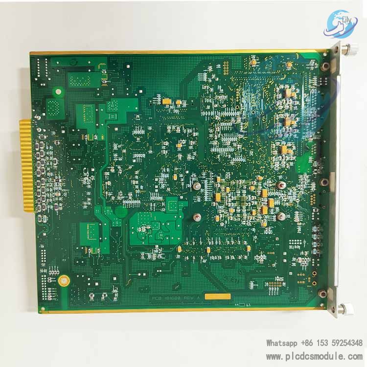
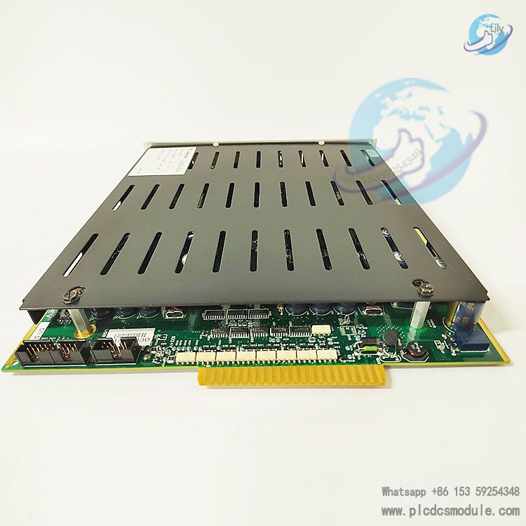
The DPU consists of a printed circuit board, which includes a Pentium-class control processor and a dedicated microcontroller for scanning I/O. There are also slots for 64MB CompactFlash and 128MB DRAM on the board.
Performance Features
The maxDPU4F has a built-in multi-speed processing system, allowing objects to be executed in three different time categories, ranging from as fast as 10 milliseconds to 0.5 seconds. The Data Point Management System (DPMS) tracks the object size and total execution time for each time category.
I/O Bus Interface
It adopts a Motorola 68332 32-bit I/O processor and a Field-Programmable Gate Array (FPGA) to interface with the Model IOP I/O bus and the I/O Bus Expansion Module (BEM) for remote I/O applications. Each electrical bus can accommodate up to 60 Model IOP I/O modules. The maximum length of the Model 564 I/O bus is 30 feet, and the length of the remote I/O link using a fiber optic extender can reach 2000 meters.
Database and Communication
Fully Self-Describing Object-Oriented Database
All information about its operation is stored in the DPU's memory, including tag names, descriptions, adjustment constants, alarm limits, etc. In addition, all graphic configuration data (drawing numbers, object positions, wiring) is also stored in the DPU, ensuring that the observed configuration is consistent with the configuration installed in the DPU. Objects are stored in a fully hierarchical database, facilitating cut-and-paste modifications and protecting control strategies.
Software Backplane Compatibility
After installing the software backplane, as long as the connected system also uses the SPB protocol, the DPU can access any exposed data stored anywhere in the connected system. Peer-to-peer transmission is fast and transparent, without the need for an independent transmission agent. The software backplane uses a subscription service, and data is transmitted only when changes are detected.
Technical Specifications
Item
Details
Operating Temperature Range
0 to 60 degrees Celsius
Storage Temperature Range
-25 to 70 degrees Celsius
Relative Humidity Range
5% to 90% non-condensing
Power Supply Requirement
24Vdc ±4Vdc
Current
0.9A @ 24Vdc
Installation-related
Power Supply The DPU is powered by the main redundant 24Vdc power supply system in the maxDNA system cabinet and is installed on the input/output (I/O) backplane with maxPAC and early Model 564 input/output modules.
Installation Location In a standard maxPAC chassis, the DPU must be installed in the leftmost position of the Model IOP rack for optimal airflow. Backup cables and Ethernet communication cables should be tied to the left side of the chassis with a bending radius of at least 1 inch to facilitate easy removal of the DPU while limiting stress on the RJ45 connectors.
When using a second DPU as a backup, it should be installed vertically below the main DPU to allow connection of a 2-foot backup cable, which is secured by cable holders tied to the side of the IOP rack.
During upgrades, the DPU can be installed on the right side of a six-wide maxPAC chassis or in any slot of a four-wide Model 564 chassis. In both cases, remove all mounting hardware and terminal panels that support earlier model DPUs, and use the two mounting holes in the rear panel metal frame to install a four-wide maxPAC chassis adapter (Metso Automation #047350) in the cleared space.
Installation Features The DPU is designed to allow installation and removal with the +24Vdc power on.
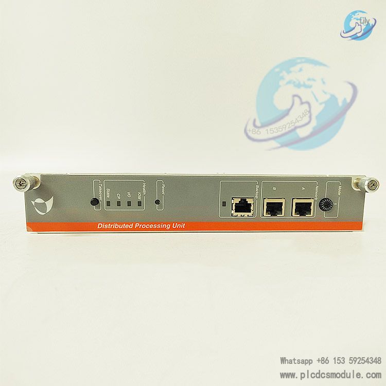
Front Panel Controls and Functions The DPU front panel contains all controls, indicator LEDs, and button switches, with no internal switches or jumpers to set during installation.
Mode Switch: A 16-bit rotary switch that is read after a DPU reset or power-up cycle to determine its operating mode and is also read during online operation, allowing the mode to be set to "Run", "Lock", or "Offline".
maxNET Interface Ports: Dual Ethernet 10/100Base-T ports for interfacing with the maxNET communication network. DPU communication can be configured as 10Mbit full-duplex, 100Mbit full-duplex, or auto-negotiation.
Network Status LEDs: Indicate the status of maxNET network A and B links.
Backup Port: A 100MB Ethernet interface used to transfer database information to the hot-standby DPU. Two DPUs are connected through this port using a custom Category 5 Ethernet cable (Part No. 050292), and status signals are also passed between DPUs through this port to indicate which DPU is in control.
Backup LED: Displays the redundancy status of DPUs configured as a backup pair.
Serial Port (Optional): An 8-pin RJ45 connector that supports RS232 signal levels for interfacing the DPU with external PLC-type devices.
Reset Button: Pressing this button will cause the DPU to stop control and perform a reset cycle. Pressing for less than 2 seconds, the DPU will save the current configuration database and then reset (soft reset); pressing for more than 3 seconds, the DPU will reset immediately (hard reset).
IOM Status LED: Indicates the operating status of the IOM processor.
I/O Status LED: Indicates the status of I/O bus transactions.
CP Status LED: Reports the health of the control processor.
Status LED: Reports the current control status of this DPU.
Takeover Button: Pressing the takeover button can force a previously inactive DPU to become active. Pressing the takeover button on an inactive standalone DPU (i.e., backup not enabled), the inactive DPU will become active regardless of its health status, database, or key switch position; pressing the takeover button on the inactive DPU of a DPU pair (backup enabled), as long as the inactive DPU is hot, it will become active regardless of its health status or mode switch position. Pressing the takeover button on an active DPU has no effect.
IRIG-B Port (Optional): A BNC connector that supports interfacing with a GPS receiver, this option allows synchronization with global time.
Front Panel Input/Output Connections The DPU chassis front panel contains all input/output connections, including two 10/100 Ethernet ports, a backup link port, an optional serial port, and an optional IRIG-B interface port.
Ethernet Network Connections: The DPU chassis contains two 10/100 Ethernet ports using RJ-45 connectors for interfacing with the maxNET communication network. Network A and Network B operate as independent networks; a failure on one network or processor will not affect the operation of the other nor cause DPU failover. Ethernet messages are sent/received based on the DPU's Ethernet address with minimal control processor intervention.
Backup Link: A 100 Mbps Ethernet link used to transfer database information between the active DPU and the inactive standby DPU. DPU backup pairs are connected through the backup link's RJ-45 connector using a custom Category 5e cable (Metso #050292). The secondary DPU is typically installed in the lower chassis directly below the main DPU.
Serial Port: The DPU front panel contains a serial port using an 8-pin RJ45-style connector, which supports redundancy. When using a DPU backup pair, the serial port operates only when the DPU is "Active"; the RS232 driver on the "Inactive" DPU is turned off.
IRIG-B Interface Port (Optional): The DPU front panel optionally includes an IRIG-B port for connection to an external time source. The connector is a BNC, transformer-coupled on the DPU.
Redundant Operation In a redundant configuration, two DPUs are connected to form a backup pair, with one DPU designated as the primary unit and the other as the secondary unit. The IP address of the secondary DPU is always one number higher than that of the primary DPU, with the primary unit always having an even address and the secondary unit an odd address.
Automatic Failover: When the primary DPU encounters a critical diagnostic alarm or communication between the primary and secondary DPUs is lost, process control is automatically transferred from the primary DPU to the secondary DPU. However, if the secondary DPU itself encounters a critical diagnostic alarm, it will refuse control unless the primary DPU is powered off or reset.
Manual Takeover: To manually command either DPU to take over control, press the takeover button on the front panel of that unit. Manual takeover occurs only if the inactive DPU is healthy enough to take over control; if there is a critical diagnostic alarm or fatal alarm condition in the inactive DPU, the takeover button will be ignored.
Software Installation The DPU uses CompactFlash to store and retrieve all software and configuration information. CompactFlash is non-volatile and can be removed to update configurations from one DPU4F or move configurations to another DPU4F. The CompactFlash is 64 megabytes, industrial-grade, operable in harsh environments, and supports a large number of write cycles. When replacing CompactFlash, be sure to use Metso Part No. 050263.
There are two basic methods to update CompactFlash:
When the DPU is installed in the I/O chassis, update CompactFlash through the Ethernet network. Mode "E" on the DPU is used to update software, and mode "C" on the DPU is used to update software and change the entire configuration file on the DPU; mode "C" even allows changing the IP address.
When the DPU is not installed in the chassis, update through a CompactFlash reader/writer connected to the USB port of the maxSTATION.
Startup Process Standalone DPU Startup: Ensure the DPU is fully configured before being allowed to take over control; configuration must be completed before allowing it to enter the online state.
Backup Pair DPU Startup: When starting a backup pair of DPUs, it is advisable (but not mandatory) to start the primary DPU first and ensure it is operating normally before starting the secondary DPU.
DPU Replacement in a Backup Pair: When replacing a DPU in a backup pair, the new unit must be prevented from gaining control until it is properly configured and updated to ensure no unexpected failover occurs during the replacement process.
DPU Restart After Failover: If the inactive DPU detects a problem with the active DPU, it will immediately take over process control and force the other DPU to become inactive. If the initially active DPU is still running, it will detect the loss of control and enter offline mode, setting its status LED to red. In this mode, the DPU will not warm up from the new active DPU unless manually intervened.
Alarm Notification Diagnostic alarms originating from the DPU are published as remote alarms on the maxSTATION alarm list, and certain fatal diagnostic alarms are also indicated by the DPU front panel LEDs.
IRIG-B Interface (Optional) IRIG-B is an international time signal standard; many vendors sell highly accurate clocks that generate IRIG-B signals. IRIG-B is also available as an output from many GPS satellite receivers, and the accuracy of this IRIG time signal is typically within microseconds.
The maxDPU4F can be optionally equipped with an IRIG-B input (models PDP406 and PDP408, DPU component #181551). These DPUs have a BNC connector through which the IRIG-B signal is applied, along with internal circuitry for decoding the signal. Once the signal is decoded, the DPU uses it as the basis for its internal clock. Typically, the IRIG DPU is designated as the time master (via database settings), which broadcasts accurate time to the remaining DPUs, DBMs, and direct access workstations in its domain. In this way, the entire domain can be synchronized with an accurate clock.
IRIG signals should be applied to both the master and slave of the maxDPU4F pair to provide a redundant time source in case one of the DPUs fails.
video display
Customers who purchased this product are also browsing the following products:


 3005319639