Note; All products on this site are special products, the market price has been fluctuating, the specific customer service offer shall prevail, because the product is a new product, the picture is not a real shot, please confirm with customer service before placing an order model and product, price and other details, the site used, new are for sale, please contact customer service communication.
The
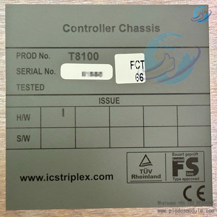
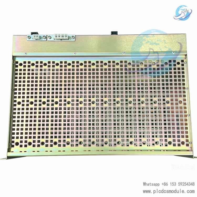
ICS TRIPLEX T8100 Trusted TMR Chassis is the core hardware of the Trusted Safety Instrumented System (SIS) under Rockwell Automation. It is specially designed for processors, I/O modules and interface modules adopting the Triple Modular Redundancy (TMR) architecture, and serves as the standard mounting base for Safety Instrumented Function (SIF) systems.
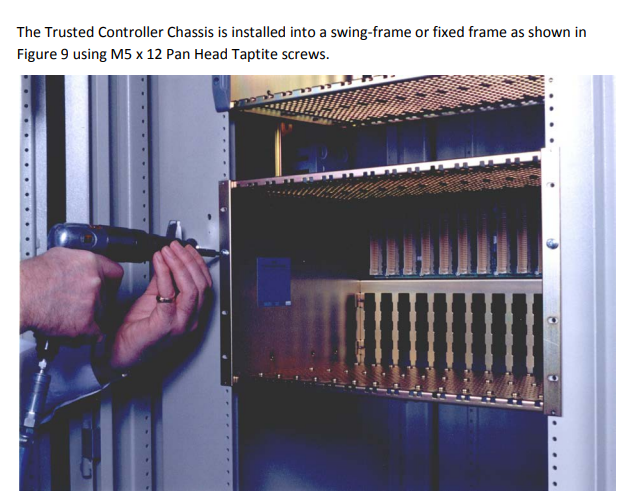
This chassis supports two mainstream mounting types: swing rack and fixed rack. Rear panel mounting is also available when used with the T8380 panel mounting kit. It is built with an Internal Module Bus (IMB) backplane, which provides electrical interconnection, signal transmission and power supply for all installed modules. It is widely deployed in safety control systems for the process industry.
The product is compatible with Trusted firmware version 3.6.1. It contains no field-repairable internal components, delivering a highly reliable and easy-to-deploy hardware integration solution for industrial safety applications.
Download
Key Features
1. Slot & Hardware Specifications
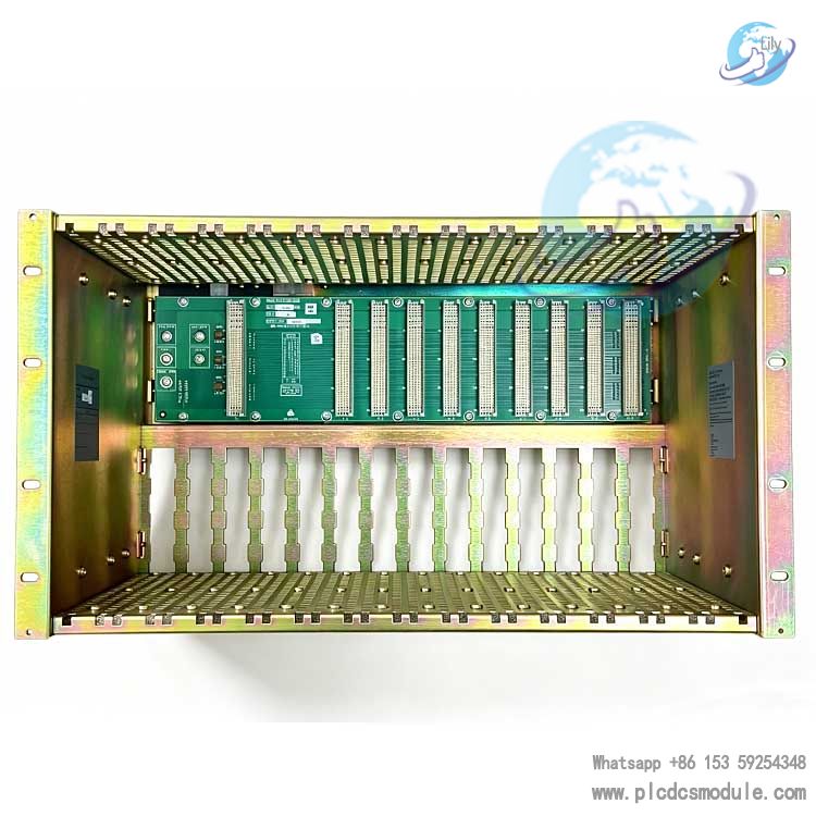
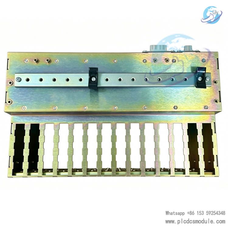
Slot ConfigurationEquipped with 2 pieces of 90mm triple-wide slots for installing Trusted TMR processors. There are 8 reserved 30mm single-wide slots for I/O modules, communication modules and interface modules. The chassis supports a maximum combination of 8 single-wide modules plus 2 TMR processors. Slots are numbered sequentially from left to right in logic. The first processor slot is designated Logic Slot 0, and the remaining I/O and interface slots are Logic Slots 1 to 8.
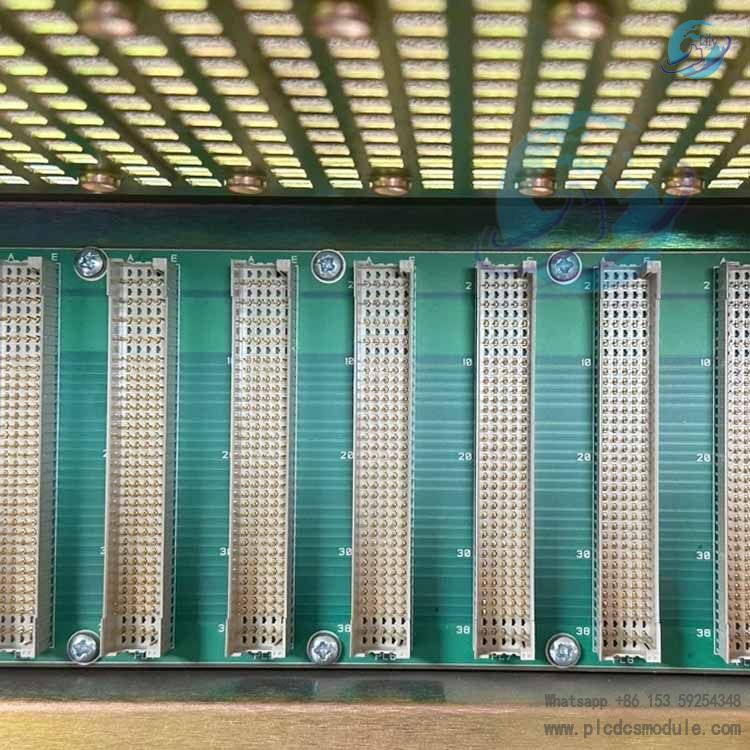
Interface SpecificationsThe backplane is fitted with DIN 41612 standard I/O port connectors, supporting four wiring specifications: 32-channel, 48-channel, 64-channel and 96-channel. Modules adopt self-aligning high-density connectors to connect with the backplane, enabling easy insertion and removal as well as stable connection.
Physical ParametersOverall dimensions: 483mm (W) × 268mm (H) × 312mm (D); Weight: 5kg. A 90mm clearance shall be reserved between adjacent chassis for heat dissipation. Ground terminals are arranged at the rear of I/O connectors, which can be secured with standard screws for grounding.
2. Electrical & Environmental Parameters
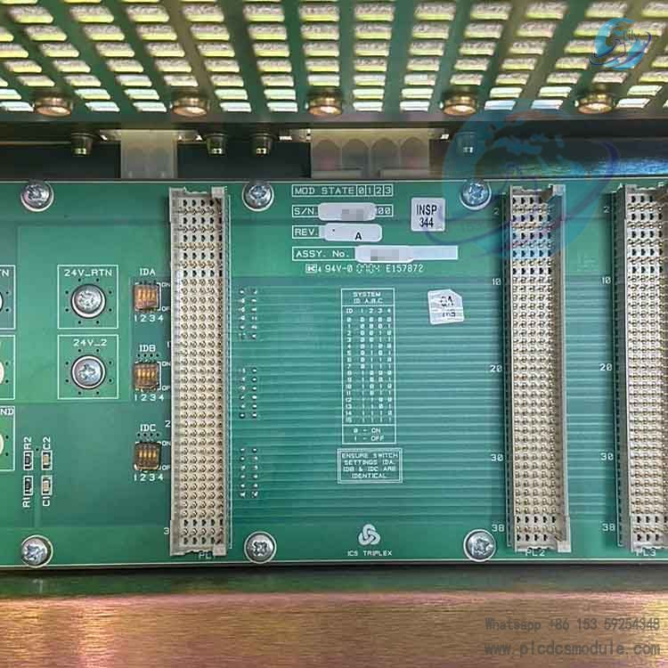
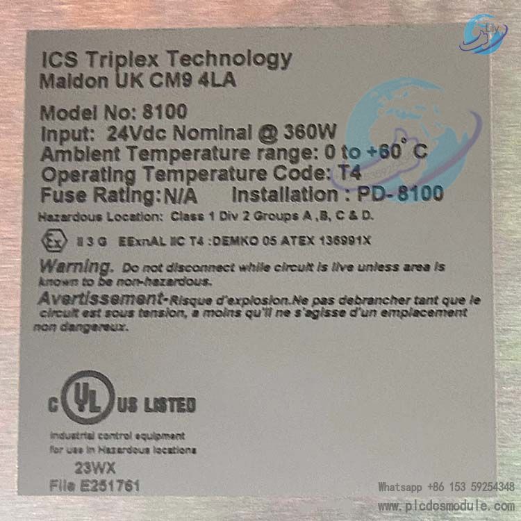
Power Supply RequirementsOperating DC voltage range: 20~32V. It adopts dual redundant external 24Vdc power supply with a 20A external fuse. Two sets of terminal blocks TB1 and TB2 on the backplane are used to connect the two redundant power supplies, providing centralized power for all modules.
Bus DesignAn integrated Internal Module Bus (IMB) backplane is adopted. All bus signals except power supply are transmitted in triple redundancy. Signal termination circuits are built in both ends (Slot 1 and Slot 10) of the backplane to optimize signal integrity and prevent interference caused by high-frequency signal reflection.
Environmental RatingsOperating temperature: 0℃ ~ +60℃; Storage and transportation temperature: -25℃ ~ 70℃. Relative humidity for operation, storage and transportation: 10% ~ 95% (non-condensing). It is fully applicable to continuous operation in industrial environments.
3. Protection & Additional Functions
Safety ProtectionThe circuit boards of modules contain electrostatic-sensitive components, and the whole chassis is designed with anti-static protection. Warning labels for electric shock, high temperature and explosion hazards are attached to the device, complying with relevant codes for use in hazardous explosive areas.
SmartSlot Redundancy FunctionChassis of Version 2 and above support cross-chassis SmartSlot configuration. Multiple chassis can be connected via TC-006 dual I/O SmartSlot cable to unify the IMB zero potential of all units. One spare slot can provide redundant backup for multiple main modules, so as to improve space utilization.
Version & FirmwareCompatible with Trusted Release 3.6.1. DIP switches for system configuration are reserved on the backplane (sealed at factory and prohibited from modification). All configurations must be completed via host computer software.
Product Advantages
High-reliability Redundant ArchitectureThe core bus signals adopt triple redundancy design, and the external 24 VDC power supply is configured with dual redundancy. Combined with backplane termination circuits to suppress signal reflection, it greatly reduces risks of signal failure and power outage in industrial environments, meeting the high availability requirements of safety systems.
Flexible Mounting CompatibilityIt supports three mounting methods: swing rack, fixed rack and rear panel mounting. Featuring fewer accessories and fast assembly, it requires no complex tools for on-site installation and adapts to various cabinet layout requirements.
High-density Modular LayoutSlots are clearly partitioned to accommodate TMR processors and multiple I/O & interface modules simultaneously. Supported by SmartSlot intelligent redundant slot sharing technology, it maximizes module integration density within limited space.
Maintenance-free with Passive Heat DissipationConvection cooling is realized via the chassis structure. There are no wearable moving parts such as fans inside, and no field-repairable components, which cuts down later maintenance workload and potential failure points.
Adaptable to Harsh Industrial EnvironmentsWith a wide operating temperature and humidity range, as well as built-in anti-RFI and anti-static designs, it satisfies environmental standards for high-risk industrial sites like chemical and power plants, delivering outstanding operational stability.
Application Scenarios
As the fundamental hardware of the ICS TRIPLEX Trusted safety system, the T8100 chassis is mainly deployed for Safety Instrumented Systems (SIS) in the process industry. Its key application scenarios are listed below:
Petrochemical IndustryApplied to Emergency Shutdown Systems (ESD), Fire & Gas Detection Systems (F&G) and Burner Management Systems (BMS) for refining units, oil & gas fields and tank farms, to prevent safety hazards such as explosion and leakage.
Power IndustryUsed for safety protection control and boiler safety monitoring systems of thermal power and gas turbine units, ensuring stable and safe operation of generator sets.
Coal Chemical & Fine Chemical IndustryServes as interlock protection systems for high-pressure reactors and synthesis units, suitable for hazardous explosive working conditions.
Process Industries (Pharmaceuticals, Papermaking, etc.)Provides safety interlock and process anomaly protection for production lines to safeguard personnel and equipment.
Offshore PlatformsDeployed in safety control systems for offshore oil and gas platforms, capable of withstanding harsh marine conditions including high humidity and salt spray.
Basic Operation Guide
1. Chassis Installation Procedures
Rack Mounting (Swing / Fixed Rack)
Secure the chassis to the rack with M5×12 pan head self-tapping screws, and prioritize using the inner holes of mounting lugs for fixation. After all chassis and fan brackets are aligned, install plastic decorative lugs via outer holes. A 90mm heat dissipation gap must be reserved between adjacent chassis when installed side by side.
Rear Panel Mounting
Adopt the optional T8380 panel mounting kit (including a pair of brackets with rear lugs). Fasten the brackets with M5 screws first, then mount the T8100 chassis onto the front lugs of the brackets to complete rear panel installation.
2. Module Assembly Process
Anti-static Preparation
Operators must wear an anti-static wrist strap. Do not touch exposed module pins with bare hands, and disassembly of modules is prohibited.
Module Insertion
Slide TMR processors and I/O modules steadily into designated slots along the upper and lower guide grooves of the chassis. Ensure the U-shaped grooves on module housings fully engage with the chassis guide structures.
Module Locking
Fasten the built-in ejector handles to lock modules; modules without handles are fixed in place upon full insertion. Processor modules support active/standby mode. When two processors are installed, the left slot acts as the primary running module by default.
3. Power & I/O Wiring
Redundant Power Wiring
Connect two independent 24 VDC redundant power supplies to terminal blocks TB1 and TB2 on the chassis backplane respectively. A 20A fuse shall be equipped for the external circuit.
I/O Connector Wiring
Select DIN 41612 connectors of appropriate specifications according to on-site signal channels. Fasten the grounding end of connectors to the cable brackets at the rear of the chassis with M5×10 pan head self-tapping screws to ensure reliable grounding.
Cross-chassis SmartSlot Wiring
For multi-chassis linkage, use TC-006 cables to connect Molex ports on the rear of each chassis to unify the IMB zero potential. The crimped ends of cables shall be connected to common grounding terminals.
4. Routine Maintenance Specifications
- No user-serviceable parts are contained inside the chassis. Replace the entire unit in case of failure. Unauthorized disassembly of the backplane and circuit assemblies is forbidden.
- Do not plug/unplug modules or disconnect wiring in flammable and explosive areas while the system is powered on, to prevent electric sparks and potential explosions.
- Attach RFI warning signs around the equipment. Handheld communication devices are not allowed near operating modules.
- Regularly inspect terminal screws and grounding fasteners for looseness. Keep ventilation passages free of dust and debris to guarantee normal convection heat dissipation.
Product Comparison
| Comparison Items | T8100 Standard Controller Chassis | T8110 Expansion Chassis | T8120 Compact Controller Chassis |
|---|
| Core Positioning | Main controller chassis, accommodates TMR processors and I/O modules | Dedicated I/O expansion chassis without processor slots | Compact main chassis for small control cabinets |
| Slot Configuration | 2 triple-wide slots for TMR processors + 8 single-wide I/O slots | All single-wide slots for I/O and interface modules; no processor slots | Reduced slot layout for small-scale safety systems |
| Bus Architecture | Triple-redundant IMB bus with dual redundant power supply | Compatible with IMB bus; inherits redundancy configuration from the main chassis | Streamlined IMB bus with core redundancy retained |
| Mounting Methods | Swing rack, fixed rack and rear panel mounting | Rack mounting only; incompatible with panel mounting kits | Primarily rack mounting, suitable for narrow cabinets |
| SmartSlot Function | Fully supports cross-chassis intelligent redundancy | Supported, requires TC-006 cables connected to the main chassis | Supports local SmartSlot only; cross-chassis function unavailable |
| Application Scenarios | Main control unit for medium and large-scale SIS | I/O point expansion for medium and large-scale systems | Small units and single-loop safety control systems |
| Dimensions & Weight | Standard 19-inch rack, 5kg | Standard rack size, slightly lighter weight | Compact size and lighter weight |
Summary
The T8100 serves as the primary main controller chassis for the Trusted system, integrating both processors and I/O modules with the highest versatility. The T8110 functions solely as an I/O expansion unit for expanding I/O points. The T8120 is designed for compact applications with simplified slots and functions.
For large-scale projects, the typical configuration is T8100 main chassis plus multiple T8110 expansion chassis. The T8120 is the preferred choice for small standalone control loops.
Frequently Asked Questions (FAQ)
Q1: What accessories are mandatory when purchasing the T8100 chassis?A: For basic operation, a 24 VDC redundant power supply and 20A external fuse are required. The T8380 panel mounting kit is a must if rear panel installation is needed. For multi-chassis SmartSlot redundancy, the TC-006 dual I/O SmartSlot cable is additionally required. Standard modules and connectors shall be selected separately according to actual I/O points.
Q2: Which firmware versions are compatible with the T8100? Can new and old modules be used together?A: This chassis is officially compatible with Trusted Release 3.6.1 firmware. It supports the full range of Trusted TMR processors and standard I/O modules. Qualified new and legacy modules can be mixed in one chassis, while all system configurations must be completed via the host software.
Q3: Are there special requirements for power supply voltage? Can 220V AC be used for direct power feed?A: Direct 220V AC power supply is not supported. The rated operating voltage is 20~32 V DC, so an external industrial 24 VDC power unit is mandatory. Dual redundant power input is required; operating on a single power feed will downgrade the system safety level.
Q4: What is the maximum quantity of I/O modules and processors for one T8100 chassis?A: It can accommodate up to 2 Trusted TMR processors (occupying 2 triple-wide slots) plus 8 single-wide I/O/interface modules. No spare slots are available for extra modules when fully configured.
Q5: Can the three DIP switches on the backplane be adjusted manually?A: Adjustment is strictly prohibited. These DIP switches are reserved functions and sealed with adhesive tape at factory. Manual modification will cause abnormal bus communication and system configuration, resulting in equipment failure.
Q6: What safety rules apply to module insertion and removal? How to operate in hazardous areas?A: Never hot-swap modules in flammable and explosive hazardous areas. Wear an anti-static wrist strap and avoid touching module pins when handling modules in regular areas. It is recommended to record slot numbers before disassembly to prevent misplacement and logic errors.
Q7: How to resolve abnormal heat dissipation and high chassis temperature during operation?A: First verify the standard 90mm heat dissipation gap between chassis and clean dust and debris around air inlets and outlets. Ensure all modules are fully inserted and latched. This chassis adopts convection cooling with no fan required. If overheating persists, check whether the ambient temperature exceeds the operating range of 0~60℃.
Q8: How to troubleshoot communication faults during multi-chassis SmartSlot linkage?A: First check the connection of TC-006 cables and the tightness of rear Molex ports. Confirm all chassis are Version 2 or above. Verify unified IMB zero potential and reliable grounding. Finally, check SmartSlot parameters via the system configuration software.


 3005319639