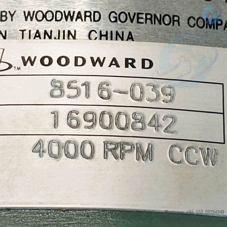
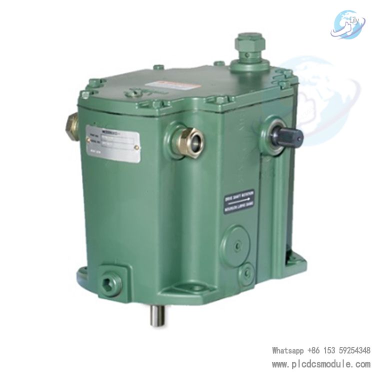
Note; All products on this site are special products, the market price has been fluctuating, the specific customer service offer shall prevail, because the product is a new product, the picture is not a real shot, please confirm with customer service before placing an order model and product, price and other details, the site used, new are for sale, please contact customer service communication. 8516-039 Governor Control, as a member of Woodward TG-13 series governors, is a mechanical-hydraulic governor specifically designed for steam turbine control, suitable for scenarios without isochronous (constant speed) operation. The governor output is provided through serrated terminal shafts extending from both sides of the housing, with a maximum terminal shaft stroke of 40 degrees, and the recommended stroke from no-load to full-load is 2/3 of the total stroke. Within the full 40° stroke range, the maximum working capacity reaches 12.2 ft-lb (16.5 J), and the internal oil pressure is 1034 kPa (150 psi). This governor can operate within standard speed ranges such as 1100-2400 rpm, 2400-4000 rpm, and 4000-6000 rpm. The speed range can be set according to customer requirements when ordering, but operating below the specified speed range will result in partial loss of output torque and performance, while operating above the specified speed range may cause overheating and component wear. The governor housing is available in two materials: cast iron and die-cast aluminum. Speed droop, a key parameter to ensure the governor's stable operation, is preset by the factory but can be adjusted internally. It offers two speed regulation methods: screw speed regulation (standard configuration) and lever speed regulation (optional configuration).
Data sheet
 8516-039.pdf
- Upon equipment arrival, inspect the packaging and appearance to ensure no damage. Since the governor is factory-tested, adjusted, drained, sealed, and painted, internal components are protected by an oil film for rust prevention, and external shafts are coated with spray lubricant. No internal cleaning or flushing is required before installation.
- For long-term storage, fill with oil and perform anti-corrosion packaging as required by Woodward Manual 25075 based on environmental conditions.
- The rotation direction of the drive shaft is determined by observing from the top of the governor and must match the turbine shaft rotation direction, which is marked on the governor nameplate.
- Adjustment methods for different governor structures vary:
- For TG governors where the pump eccentricity is not machined on the base, remove the governor, drain the oil, and adjust the position of the eccentric ring inside the pump housing.
- For TG governors with pump eccentricity machined on the base, rotate the pump housing assembly 180 degrees, but take care to prevent the pump shaft from detaching from the ball head drive shaft to avoid dangerous overspeed.
- The governor can be installed vertically or horizontally:
- When installed vertically, the breather/oil filler cap and drain plug are pre-installed at the factory.
- When installed horizontally, swap the positions of the cap and plug and tighten them to prevent leakage, ensuring the oil level gauge is positioned at the top of the governor.
- Ensure the governor drive shaft is accurately aligned and concentric with the turbine shaft. Use appropriate gaskets and drive couplings to avoid damaging the drive shaft.
- Before the first run, ensure all installation steps are completed. During startup, prepare emergency shutdown measures to prevent prime movers (such as engines or turbines) from losing control or overspeeding.
- Typically, for new or overhauled governors, only oil filling and rated speed setting adjustment are needed before use, as other adjustments are completed at the factory. Start by reducing the speed setting, slowly opening the steam valve, checking the turbine speed, adjusting it to the rated speed, and verifying the governor's stability.
- Speed droop is a critical parameter for the governor's stable operation, calculable via a specific formula. The factory-preset 6% droop setting (corresponding to a 20° terminal shaft stroke) suits most applications.
- If the governor shows instability or difficulty responding to load changes, adjust the droop adjusting lever as follows: shut down the turbine, remove the cover, loosen the fixing screws to move the lever, tighten the screws and reinstall the cover, add oil, observe operation, and repeat adjustments until satisfied.
- For governors equipped with an OTD, adjust according to the application's trip speed. Steps include: shutting down the turbine, removing the cover, using specialized tools to operate the cam and pushrod, adjusting at the turbine's rated no-load speed to achieve the set trip speed, and setting an additional ultimate speed stop.
- When testing the overspeed function with OTD, follow specified procedures. If issues occur (e.g., trip speed not reached or trip function failing), adjust or repair and retest.
- Internal components mainly include an oil pump, oil accumulator, speed governor spring, ball head and pilot valve bushing assembly, pilot valve plunger, servo piston, droop adjustment device, speed adjustment device, terminal lever, and shaft.
- During operation, the oil pump (driven by the turbine) draws oil and builds pressure. Oil flow and pressure changes control the servo piston's movement, adjusting the terminal shaft position to regulate the steam turbine. For example, when speed changes, the centrifugal force of flyweights moves the pilot valve plunger, controlling oil flow to the servo piston and adjusting steam flow.
- Governor operation faults often manifest as turbine speed variations, though not all speed changes stem from governor issues. When problems arise, inspect all components, adjustment settings, and turbine operation.
- Perform visual checks on linkages, oil level and quality, and turbine operation. For different fault symptoms (e.g., turbine fluctuation, terminal shaft jitter, or difficulty accepting load), analyze possible causes and take corrective actions, such as adding/replacing oil, adjusting linkages, or readjusting droop.
- When ordering replacement parts, provide the governor's serial number, part number, manual number, and the part's reference number and name in the parts list.
- The manual details replacement parts lists for governors of different models and configurations, including various screws, washers, seals, bearings, springs, etc. For example, the TG-13 series (including 8516-039) covers replacement parts from the housing to internal precision components for different structural types.
Customers who purchased this product are also browsing the following products:
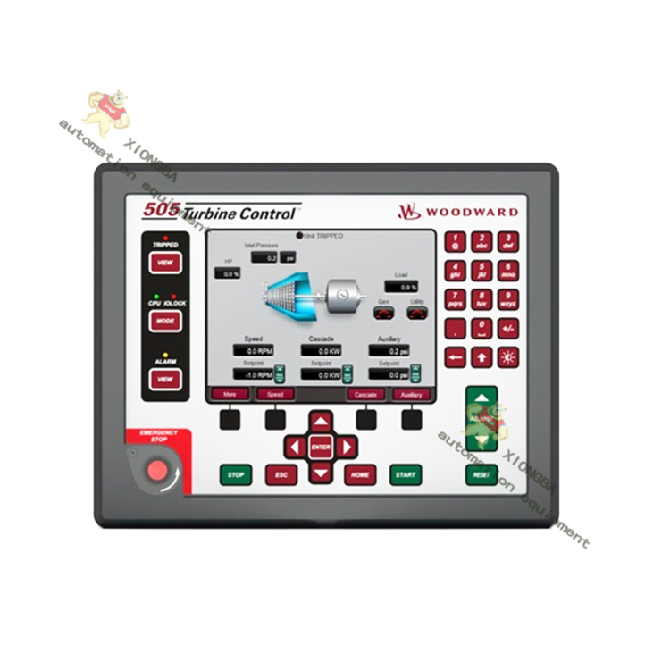
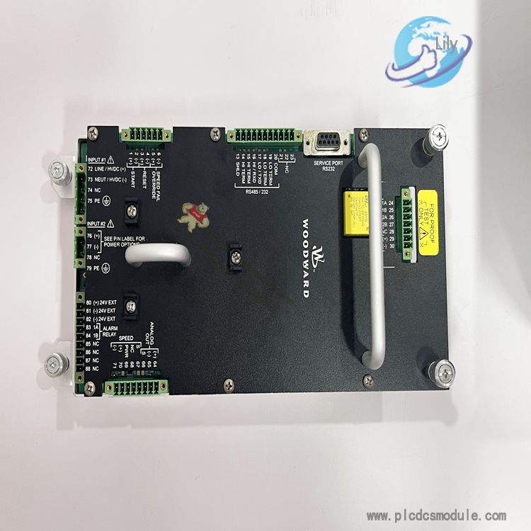
woodward 9907-167 505E Digital Governer with controlled
Woodward 5466-1045 Plus Digital Controller
GE IS200JPDMG1ACC Mark VI Power Distribution Board
Bently Nevada 146031-02 3500/22M 100Base-FX (Fiber Optic) I/O Module


 3005319639