


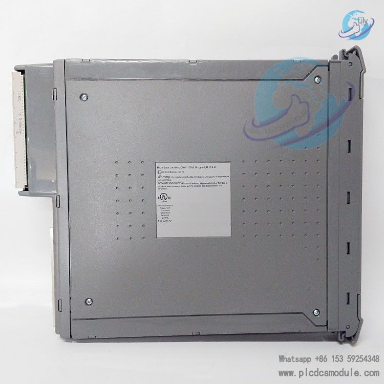
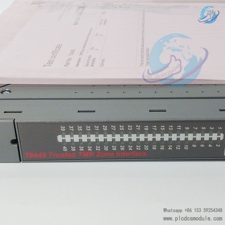
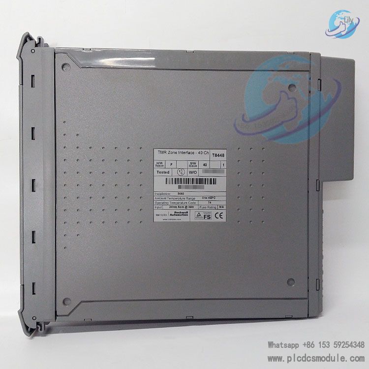
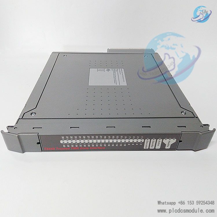
The ICS Triplex T8448 is a high-integrity Triple Module Redundancy (TMR) zone interface module designed specifically for fire and gas protection systems. Operating at 24Vdc, it features 40 flexibly configurable input/output channels.
Connectable to various fire and gas field devices via the 8842 multifunctional field terminal assembly, it supports independent configuration of analog inputs, digital inputs, or digital outputs, meeting protection interface requirements for single or multiple fire and gas zones.
Its TMR architecture ensures fault tolerance, complemented by comprehensive automatic diagnostics and self-testing functions for reliable operation in harsh industrial environments. Certified by TÜV and compliant with IEC 61508 SIL 3 safety standards, it is ideal for safety-critical industrial scenarios with extreme demands on safety and availability.
File Download:
Core Architecture & Components
Overall Architecture Design
The module is built on Triple Modular Redundancy (TMR) technology, with each channel featuring independent redundant design to withstand single faults while maintaining normal operation. It consists of four core units that work together to realize signal processing, field connection, and status monitoring.
Key Functional Units
- Field Terminal Unit (FTU): Connects three Field Interface Units (FIUs) to a single field interface. Provides group fail-safe switches, signal conditioning, overvoltage protection, EMI/RFI filtering, and supports signal transmission and isolation for SmartSlot links.
- Field Interface Unit (FIU): Each module includes three FIUs (corresponding to slices A, B, and C). Integrates output switch structures, ADC monitoring circuits, monitors field I/O power voltage, and collects on-board "housekeeping" signals (e.g., power voltage, current consumption, board temperature).
- Host Interface Unit (HIU): Serves as the hub for the Inter-Module Bus (IMB), providing power distribution, high-speed fault-tolerant communication, and isolated interconnections between slices. Features three independent Fault Containment Regions (FCRs) to prevent fault propagation between slices.
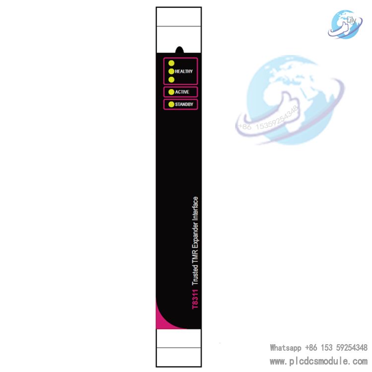
Front Panel Unit (FPU): Integrates status indicators, connectors, and a removal switch. Uses bicolor LEDs to display each channel’s operating status, fault information, overall module health, and operating mode (Active/Standby/Educated).
Core Functions & Features
Channel Configuration & Compatibility
40 TMR-configurable I/O points, with each channel independently configurable as analog input, digital input, or digital output.
- Supports 4-20mA gas detectors, fire/heat detectors, emergency break-glass devices (inputs), and dampers, extinguishing agent release devices, fire pumps (high-power digital outputs).
Compatible with 2-wire or 3-wire field devices via the 8842 terminal assembly, providing up to 5 independent programmable field device reset signals.
Safety & Reliability Design
- Equipped with 2500V pulse-withstand optoelectronic/electrical isolation barriers and channel-level overcurrent protection (no external fuses required).Group Fail-Safe Switch (GFSS) cuts off corresponding group outputs in case of two or more module faults, ensuring a safe state.
Comprehensive automatic diagnostics (channel current/voltage monitoring, switch stuck detection, field wiring/load fault diagnosis) with real-time fault reporting via front-panel LEDs and system bus.
Efficient Maintenance & Scalability
Supports online hot replacement via dedicated Companion Slot (adjacent slot) or SmartSlot (shared standby slot) without interrupting system operation.
Built-in Sequence of Events (SOE) reporting with 1ms time resolution for fault tracing and system analysis.
5 isolated power groups (8 channels each) for flexible combination to adapt to channel configurations in different fire and gas zones.
Installation & Configuration Requirements
Installation Specifications
- Install in I/O module slots of T8100/T8300 chassis. Inspect module appearance and pin integrity before installation; avoid contact with electrostatic-sensitive components.
- Use specified field cables (e.g., Companion Slot cable PD-TC200, SmartSlot cable PD-TC500). Unused output channels must be connected to 0V via a 4K7 0.5W resistor.
Keyed design: Remove keying pins from cables according to module type to ensure correct insertion into corresponding slots and prevent installation errors.
Configuration Methods
- All configurations are completed via the Engineering Workstation (EWS) using IEC 61131 tools, including I/O variable definition, module physical location setup, and channel function settings.
- Supports customization of module operating characteristics via the System.INI file (e.g., LED indication mode, default channel status, fail-safe strategy).
Configurable SOE logging for timestamp recording and monitoring of input/output status changes and line fault states.
Technical Specifications
| Category | Details |
|---|---|
| Power Parameters | Backplane (IMB) power: 20-32Vdc, 27W; Field power: 18-32Vdc, max 2A per channel, max 8A per group (0-50℃) |
| Output Characteristics | Off-state resistance: 33kΩ; On-state resistance: 1.6Ω; Minimum load current: 50mA; Switching delay: 5ms; Supports electronic latching short-circuit protection |
| Input Characteristics | Input impedance: 33kΩ; Analog resolution: 12-bit; Calibration accuracy: 0.12V (0V to VFIELD-4V)/0.48V (VFIELD-4V to VFIELD) |
| Environmental Requirements | Operating temperature: 0-60℃; Storage temperature: -25-70℃; Relative humidity: 10%-95% (non-condensing) |
| Physical Dimensions | Height: 266mm; Width: 31mm; Depth: 303mm; Weight: 1.3kg |
| Safety Certifications | TÜV certified; Compliant with IEC 61508 SIL 3; Channel isolation: 50V (continuous)/250V (fault) |
Troubleshooting & Maintenance
Fault Detection
- Field wiring faults (open circuit, short circuit, no power) are automatically identified via channel voltage/current monitoring, with the line fault bit (LINE_FLT) set to 1 and corresponding channel LEDs indicating fault mode.
Module faults are indicated by front-panel health LEDs: Single slice fault – corresponding health LED flashes red; Critical fault – LED stays red (system continues operation until module replacement).
Maintenance Operations
- Hot-swap support: Standby modules in Companion Slot configurations switch automatically; SmartSlot configurations enable multi-module replacement via shared standby slots.
- Cold-start recovery: After a dual-fault shutdown, remove and reinsert the module; normal operation resumes after processor reset.
- Active/standby module switching: Managed by the TMR processor (automatic on fault) or forced by opening the module removal switch and pressing the processor reset button.


 3005319639