


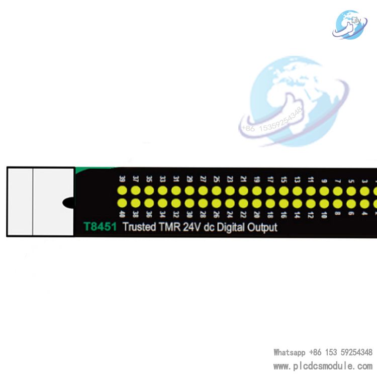
The ICS TRIPLEX T8451C is a highly reliable 24V DC digital output module, designed specifically for industrial control systems with high safety requirements. Adopting a Triple Modular Redundancy (TMR) architecture, the T8451C module is equipped with 40 independent output channels. It ensures stable operation in critical applications through comprehensive automatic diagnostics, line monitoring, and fault-tolerant mechanisms, making it widely suitable for industrial sectors demanding high availability and fail-safe protection.(T8451)
Download
| Parameter | Specification |
|---|---|
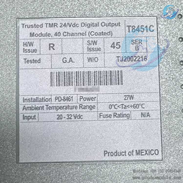
| Backplane (IMB) power supply | 20–32 V DC |
| Field power supply | 18–32 V DC |
| Power consumption | 27 W |
| Number of output channels | 40 |
| Number of power groups | 5 (8 channels per group) |
| Maximum continuous current | 2 A per channel |
| On-resistance | 1.6 Ω |
| Current measurement range | 0–2.7 A (±5% / ±5 mA) |
| Voltage measurement range | 0–30 V DC (±2 V) |
| Maximum withstand voltage | -1 V ~ +40 V DC |
| Operating temperature | 0–60 °C |
| Storage temperature | -25–70 °C |
| Relative humidity | 10%–95% (non-condensing) |
| Height | 266 mm (10.5 in) |
| Width | 31 mm (1.2 in) |
| Depth | 303 mm (12.0 in) |
| Weight | 1.3 kg (2.7 lb) |
| SOE resolution | 1 ms |
| Timestamp accuracy | ±10 ms |
| Channel crosstalk | < 1% |
| Maximum load capacitance | 3000 μF |
Core Architecture and Composition
Overall Architecture Design
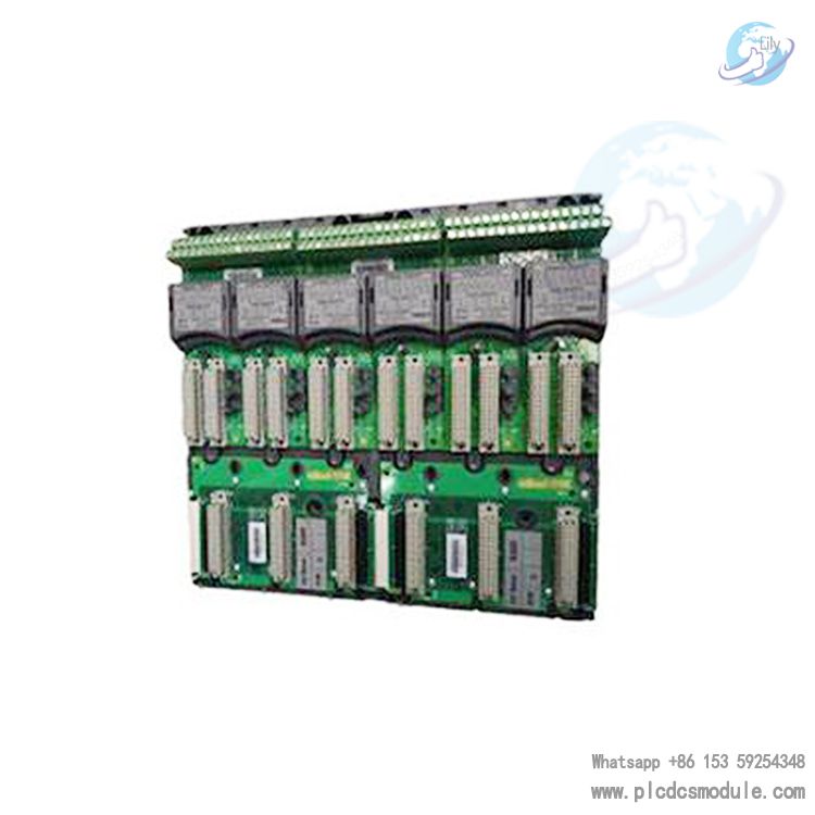
The module is constructed based on TMR (Triple Modular Redundancy) technology. All critical circuits and channels are triple-redundant. In the event of a failure in a single component or channel, the system can maintain normal operation through the redundant voting mechanism to avoid production interruption.The module communicates with the TMR processor via the Inter-Module Bus (IMB) and provides an independent field interface for connecting external devices. The overall architecture is divided into four core functional units:
Host Interface Unit (HIU)
As the core connection between the module and the IMB backplane, the HIU is responsible for power distribution, high-speed fault-tolerant communication, and data processing.The HIU comprises three independent slices: A, B, and C (Fault Containment Region, FCR). An isolation design between slices prevents fault propagation. It provides galvanically isolated serial interfaces for communication with other units, supporting redundant power sharing and local data storage.
Field Interface Unit (FIU)
Each module is equipped with three FIUs (corresponding to the three slices), which handle the actual signal interaction of the 40 output channels.The FIU integrates Σ-Δ output circuits, supporting real-time monitoring of voltage and current for each channel. It also measures “housekeeping” signals such as supply voltage, current consumption, and board temperature, providing data support for fault diagnosis.
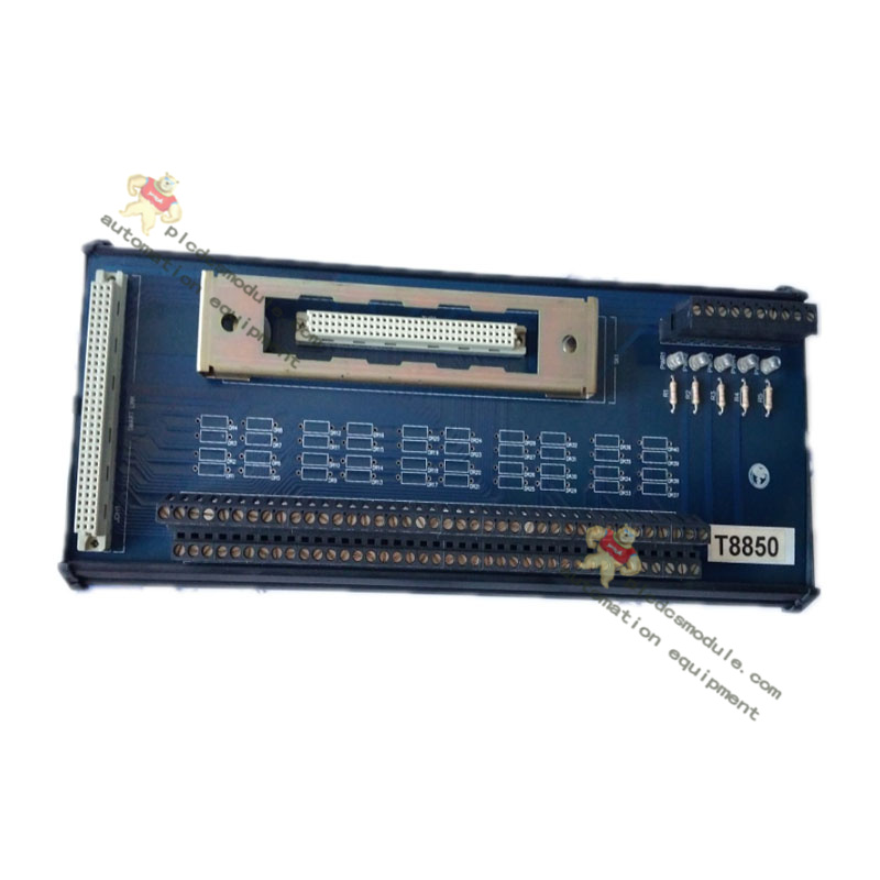
Field Terminal Unit (FTU)
The FTU consolidates signals from the three FIUs into a single field interface, providing Group Fault Safety Switch (GFSS), signal conditioning, overvoltage protection, and EMI/RFI filtering.The FTU also supports SmartSlot link transmission, providing an intelligent coordination channel for Active/Standby module switching.
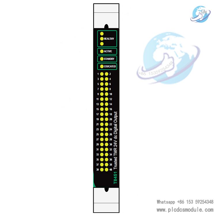
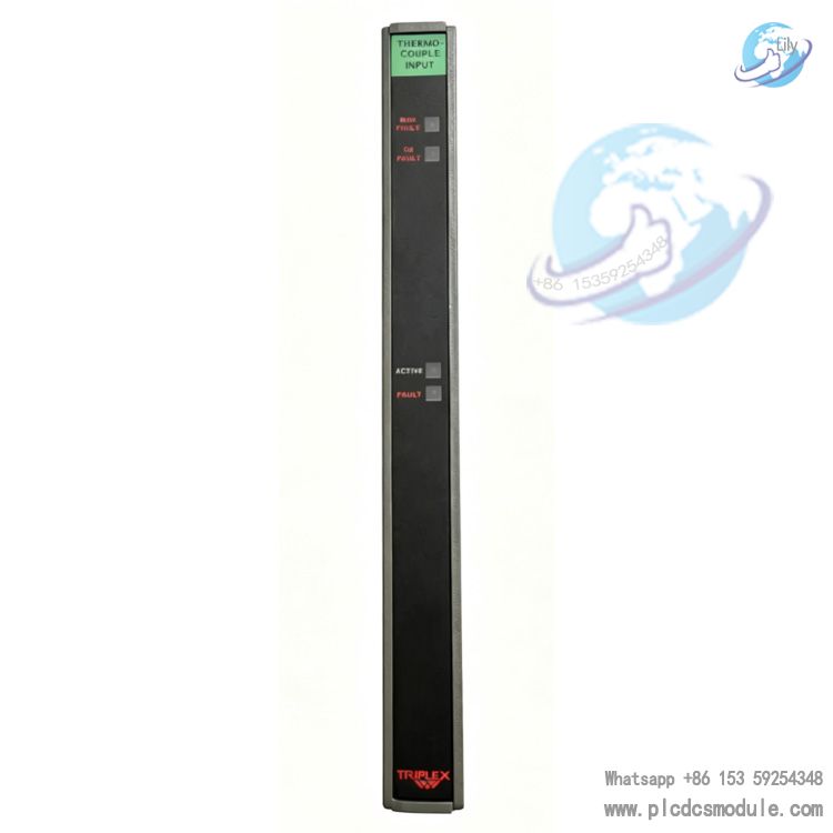
Front Panel Unit (FPU)
Integrates status indicators, removal switches, and logic control circuits.It includes indicators for slice health status, operating modes (Active/Standby/Educated), and independent status indicators for the 40 channels. The accuracy of status indication is ensured by a 2-out-of-3 (2oo3) voting mechanism.
Output Switch Structure
The module adopts a redundant switch topology. Each output channel is driven by three independent fail-safe switches (located in the three FIUs respectively).Switches are available in Normally Open (N.O.) and Normally Closed (N.C.) types, with cross-control from the “upstream” neighboring FIU to ensure that two switches remain operational to drive the load even if one slice fails.The switches use an enhanced MOSFET design and default to OFF when module power is removed. Current monitoring, overvoltage protection, and drive logic protection are implemented via resistors, Zener diodes, and other components.
Core Functions and Features
Redundancy and Fault Tolerance
- 40 TMR redundant output channels, each with triple diagnostic tests covering current, voltage measurement, and stuck-on/stuck-off fault detection.
- Supports online hot replacement via Companion Slot (dedicated adjacent slot) or SmartSlot (multi-module shared spare slot) configuration. Module replacement can be completed without shutdown to ensure system continuity.
- Group Fault Safety Switch (GFSS) groups 8 channels into one power group (5 power groups in total). When two or more faults are detected, the GFSS automatically cuts off the power to the corresponding group to ensure load safety.
Comprehensive Fault Detection and Diagnosis
- Automatic Line Monitoring: Real-time detection of open circuits, short circuits, and load anomalies in field wiring. The output channel status is determined by voltage and current measurement (status values 1–5 correspond to different faults or operating modes).
- Overcurrent Protection: Each channel is equipped with electronic latching overcurrent protection. The output is automatically turned off when sustained overcurrent is detected. Short-circuit detection (resistance < 24 Ω) can be configured via the System.INI file under power loss. Faults can be cleared by system reset or channel status toggle.
- Built-in Sequence of Events (SOE) reporting with 1 ms resolution. Timestamps are automatically recorded when the output status changes. User-configurable SOE logging is supported for fault traceability.
Electrical and Safety Characteristics
- Isolation Performance: 2500 V impulse withstand optical/electrical isolation barrier. Reinforced isolation is provided between power groups and field commons (50 V continuous, 250 V under fault conditions). No channel-to-channel isolation.
- Electrical Parameters: Maximum continuous current per channel: 2 A; minimum load current: 50 mA; output on-resistance: 1.6 Ω. Supports 0–2.7 A current measurement (accuracy ±5% / ±5 mA) and 0–30 V voltage measurement (accuracy ±2 V).
- Safety Compliance: Meets the “protective output requirements” of IEC 61131-2 and is SIL 3 certified. Suitable for industrial control applications requiring high safety levels. Direct connection to hazardous areas is prohibited; intrinsic safety barriers must be used.
Installation and Configuration
Installation Requirements and Procedure
Before installation, inspect the module for physical damage and bent pins, and record the module model, version, and serial number. Operators must be professionally trained and comply with relevant safety standards.
Installation Steps
- Ensure field cable assemblies are properly installed.
- Verify the position of the I/O module locating key.
- Open the pop-up latch.
- Insert the module and press firmly into place.
- Lock the latch.Ensure installation is smooth without resistance; avoid forced insertion.
Cable Selection
Supports Trusted I/O Companion Slot cable (PD-TC200) and SmartSlot cable (PD-TC500). Custom multi-core FTA cable specification: 0.5 mm², resistance 40 Ω/km. Unused output channels must be connected to zero voltage via a 4K7 0.5 W resistor.
Polarization and Positioning
The module uses locating pins to prevent incorrect insertion. For the T8451 model, locating pins 1, 5, and 6 on the cable must be removed to match the module’s locating holes.
Configuration Method
No physical configuration is required. All parameters are set via the Engineering Workstation (EWS) tool. The core configuration steps include:
- Use the dictionary editor in the IEC 61131 TOOLSET to define I/O variables for field output data and module status.
- Create a module definition in the I/O Connection Editor, specify the chassis/slot position, and associate channel variables.
- Define LED indication modes, channel default/fail-safe status, and other parameters via the Trusted System Configuration Manager.
Supports SOE log configuration. SOE recording for Boolean variables is enabled via the Data Dictionary Editor, and logs can be retrieved via the SOE and Process History package.
The module complex device definition includes 8 I/O boards (Rack 1–Rack 8), corresponding to output status, channel status, voltage/current measurement, fault status, housekeeping data, etc. Customization of short-circuit detection, simulation enable, and other features is supported via the System.INI file.
Application Areas
The module is suitable for highly demanding industrial control applications requiring exceptional safety and availability, including petrochemical, power generation, and rail transit.It can serve as the output control unit for critical equipment, and work with Trusted series controllers to build SIL 3 certified safety control systems.


 3005319639