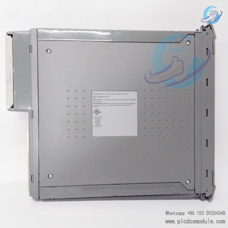
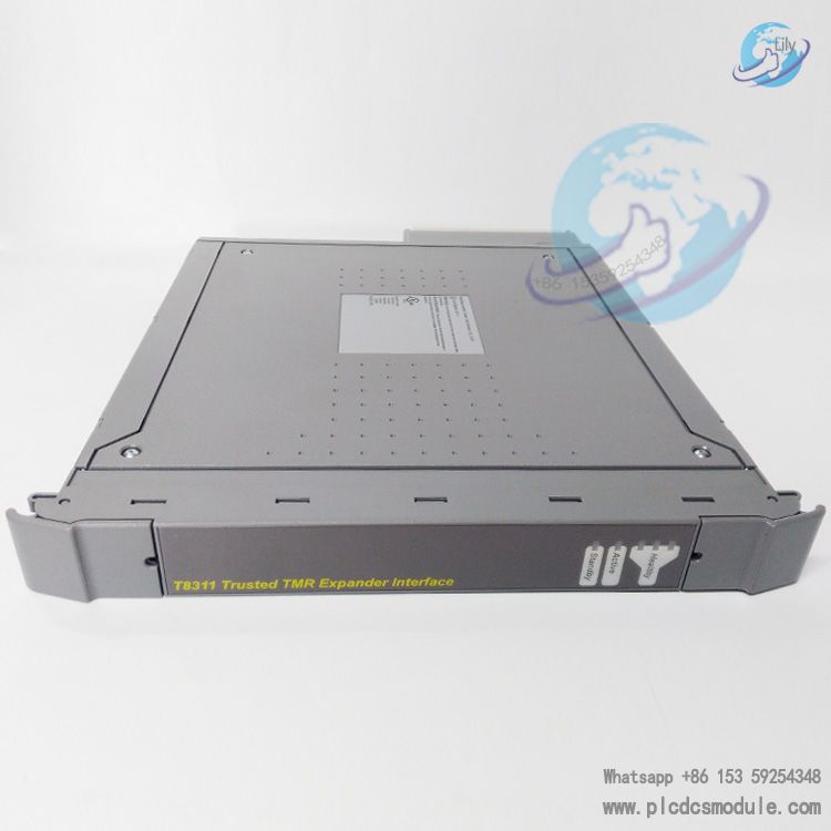
The ICS TRIPLEX T8311 Trusted TMR Expander Interface is a high-performance, high-fault-tolerance expansion interface module launched by ICS TRIPLEX for critical industrial control systems. Installed in the Trusted controller chassis, it acts as the master interface between the Inter-Module Bus (IMB) and the expansion bus within the chassis. Its core adopts a Triple Modular Redundancy (TMR) and Hardware Implemented Fault Tolerance (HIFT) architecture, which can effectively prevent single-point failures and ensure stable system operation in harsh industrial environments. It also supports the construction of multi-chassis systems via Unshielded Twisted Pair (UTP) cables, expanding I/O capacity and system functions while maintaining the fault tolerance and high-bandwidth characteristics of the IMB bus. Complying with the IEC 61508 SIL 3 safety standard and holding T2V certification, it meets the stringent requirements for safety and availability of control systems in industries such as petrochemicals, power energy and rail transit, and serves as a key component for building large-scale, complex fault-tolerant control systems.
Download

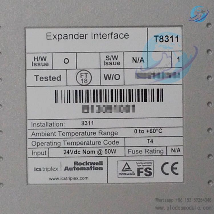
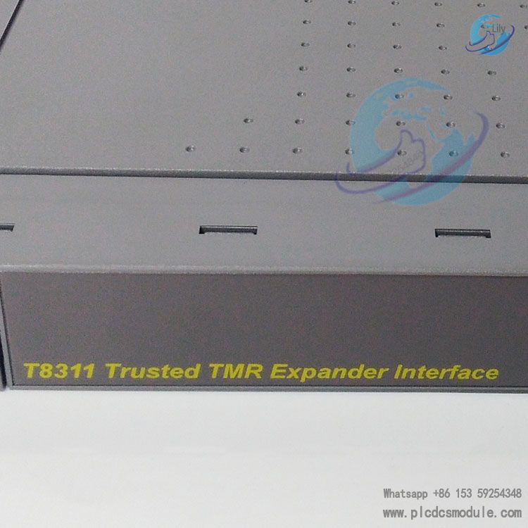
Model Decoding
- T8311: Product part number, designating the dedicated expansion interface card for the Trusted series
- Trusted: Product line brand, SIL 3-certified safety instrumented control system
- TMR: Abbreviation for Triple Modular Redundant, referring to the triple modular redundant hardware architecture
- Expander Interface: Functional definition; bridge module for communication between the main controller chassis and remote expansion enclosures
Detailed Product Specifications
Hardware Architecture Features
Operation Mode Features
Environmental & Physical Specifications
- Operating voltage range: 20 ~ 32 VDC; Total power consumption: 54 W
- Operating temperature: 0°C ~ 60°C; Storage temperature: -25°C ~ 70°C
- Humidity: Stable operation within 10% ~ 95% non-condensing
- Dimensions: 266 mm × 31 mm × 303 mm; Weight: 1.14 kg
- Backplane insulation rating: 50 V basic insulation; Integral non-user-replaceable fuse
- Installation restriction: Must be installed in standard I/O slots of the T8100 controller chassis. Installation in triple-width processor slots is prohibited to avoid permanent hardware damage.
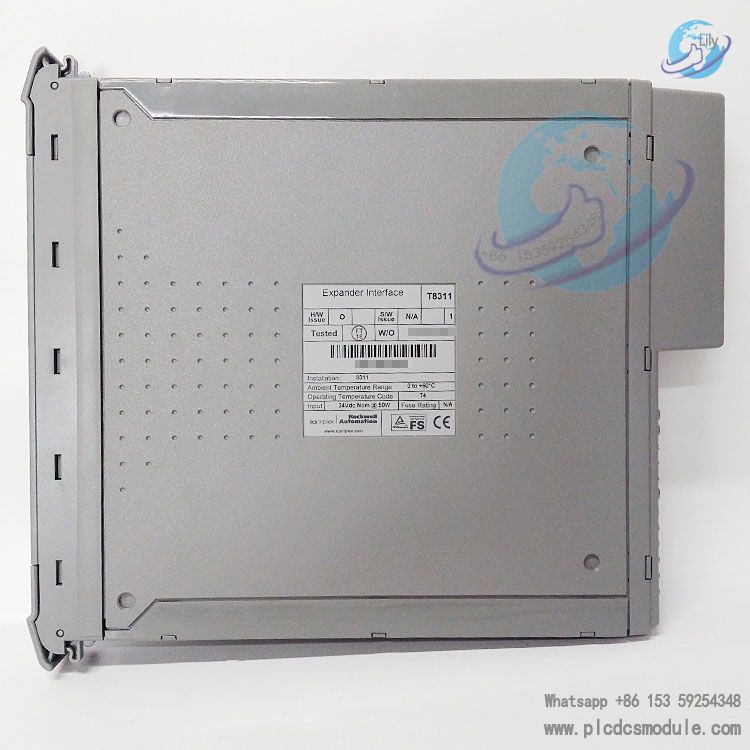
Core Product Advantages
3-2-0 Triple Modular Redundant Fault-Tolerant Architecture
Hardware-Implemented Fault Tolerance (HIFT) Design
Full-Link Galvanic Isolation
Hot-Swap Support
Multi-Layer Front-Panel Status Indicators
TÜV SIL 3 Safety Certification per IEC 61508
Dual Communication Transmission Options
Standardized Matching Adapters & Cable Assemblies
Applicable Industries
Oil & Gas Industry
ESD emergency shutdown systems and fire & gas detection interlock controls for offshore platforms and long-distance oil & gas transmission pipelines.Fine Chemical & Coal Chemical Industry
Safety interlocks for reaction kettles, pressure and temperature protection of distillation columns, and toxic gas monitoring control systems.Thermal Power & New Energy Power Plants
Turbine protection, boiler safety interlocks, and fault trip protection for generator units.Pharmaceutical Plants
Safety instrumented systems for high-risk reaction workshops and automatic control in explosion hazardous areas.Mining & Metallurgy
Safety monitoring for smelting furnaces and interlock protection against flammable gas underground.Water Treatment & Hazardous Waste Disposal
Safety shutdown interlocks for hazardous waste incineration and pipeline interlocks for high-risk chemical agents in wastewater treatment processes.
Same-brand Product Comparison Table
| Comparison Item | T8311 Expander Interface Module | T8110B TMR Processor Module | T8151B Communications Interface Module | T8800 Digital Input FTA Terminal Assembly |
|---|---|---|---|---|
| Core Function | Communication bridge between main controller chassis and remote expansion enclosures | Logic execution and safety interlock control for the entire SIS system | Data exchange with upper workstations and third-party field devices | Acquisition of 24V digital discrete signals from field site |
| Installation Location | Single-width I/O slots of controller chassis | Dedicated triple-width processor slots in controller chassis | I/O slots of controller chassis | Terminal strips in field cabinets |
| Redundancy Architecture | Triple Modular Redundancy (TMR); dual-module active/standby hot backup | Lock-step TMR operation; single unit with independent fault tolerance | TMR architecture, single-module standalone operation | No internal redundancy; TMR implemented by matching input modules |
| Safety Integrity Level | SIL 3 | SIL 3 | SIL 3 | SIL 3 certified auxiliary peripheral |
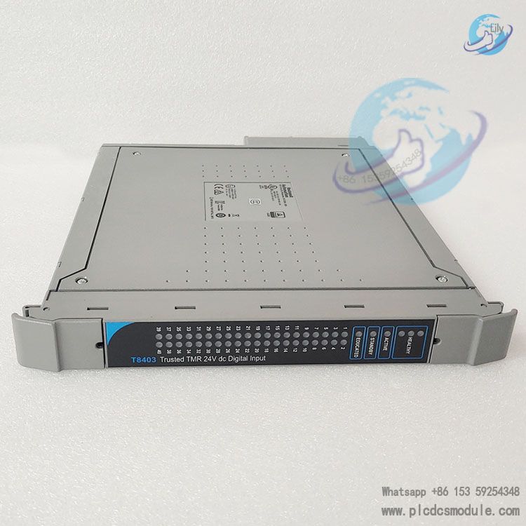
| Key Supporting Parts | T8312 adapter, TC-301/TC-302 cables, T8314 fiber optic unit | T8100 controller chassis, full range of I/O modules | T8153 communications adapter, Ethernet cables | T8403 digital input modules |
| Typical Application Scenarios | Expansion of large distributed multi-chassis safety systems | Core computing unit for all Trusted systems | Interconnection of multiple systems and data exchange with upper monitoring software | Field discrete signal collection |
FAQ
Q1: Can a single T8311 module operate independently? Is it mandatory to purchase in pairs?
Q2: The maximum transmission distance of TC-301 copper cable is 30 meters. How to realize communication with expansion enclosures if the on-site distance exceeds this limit?
Q3: Does system shutdown need to be performed in advance for T8311 hot swapping? Will safety interlock trip be triggered?
Q4: A single-channel HEALTHY red LED flashes on the front panel. Is immediate shutdown and module replacement required?
Q5: Can T8311 be installed in other Trusted chassis models, such as I/O slots of expansion enclosures?
Q6: What key parameters need to be configured for T8311 during system setup? Is complex programming required?
Q7: Multiple T8311 modules report faults simultaneously in one system. Which component shall be inspected first during troubleshooting?
Q8: What are the temperature and humidity limits for T8311 operation? Can cooling fans be installed for high-temperature working conditions?
Recommended Trusted Series Same-brand Models
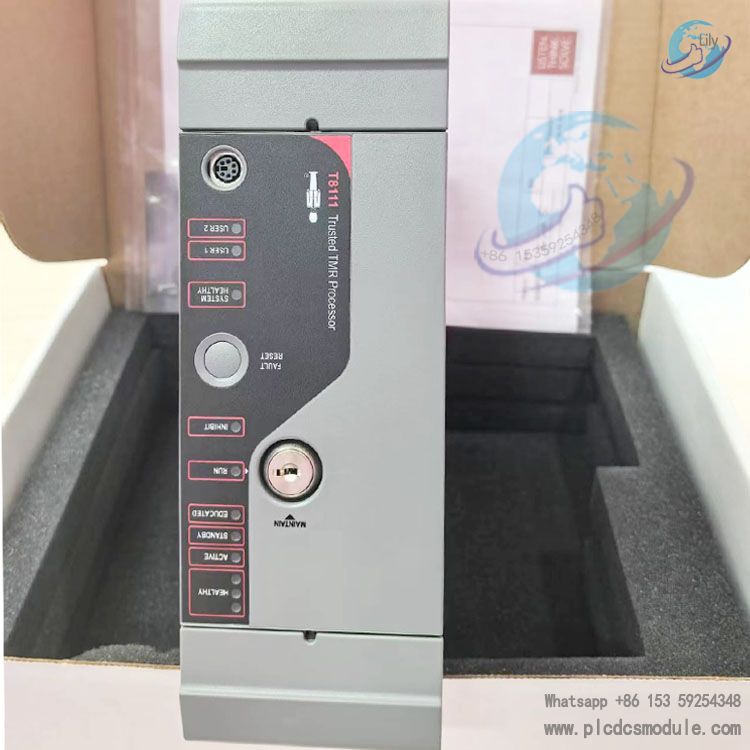
- T8110B Trusted TMR Processor Module
- T8100 Trusted Controller Chassis
- T8312 Trusted Expander Interface Adapter Unit
- T8314 Trusted Fibre TX/RX Unit
- T8151B Trusted Communications Interface Module
- T8403 Trusted Digital Input Module
- T8461 Trusted Analogue Output Module
- T8800 Trusted Digital Input FTA
- T8830 Trusted Analogue Input FTA
- T9402 Trusted Power Supply Module
- T8153 Trusted Communications Adapter
- T8442 Trusted Temperature Input Module
- T8850 Trusted Analogue Output FTA
- T8471 Trusted Digital Output Module