


It enables high-speed data interaction between master control units (such as PLCs and industrial PCs) and slave devices (drives, sensors, actuators, etc.) through the standardized Profibus-DP protocol. It supports an adjustable baud rate ranging from 9.6kbit/s to 12Mbit/s and can expand up to 125 slave devices.With features like easy installation, flexible configuration and stable operation, it is widely used in industrial scenarios requiring centralized management and control of multiple devices, including power generation, automated production lines and machine tool control. It provides an efficient and reliable distributed control communication solution for the system.
Core Communication Parameters
Communication Rate: It strictly complies with the Profibus-DP standard, with a baud rate adjustable between 9.6kbit/s and 12Mbit/s. For example, when the baud rate is 1.5Mbit/s, it only takes 6 milliseconds to complete the polling operation of 8 drives, meeting the demand for fast data interaction in industrial scenarios.
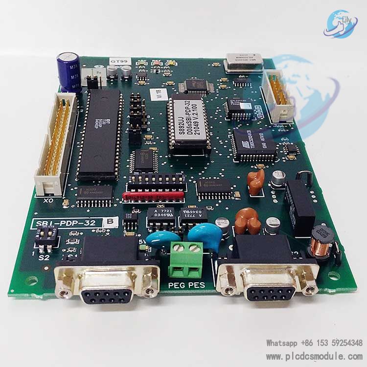
Connection Capacity: As a standard Profibus-DP physical interface board, the bus can connect up to 125 slave devices, adapting to the equipment expansion needs of large-scale industrial control networks.
Data Exchange Method: It adopts a cyclic data exchange mode. The master unit (such as PLC, PC) can stably read the input data of slave units (sensors, actuators, drives, etc.) and write output data to the slave units. Moreover, the bus cycle time is shorter than the cycle time of the central unit, ensuring the real-time response of control commands.
Hardware Configuration and Installation Related
Supporting Installation Components: A complete installation kit is provided at the factory, including 4 gaskets, 4 screws, washers, and a 40-pole flat cable with connectors. There is no need to purchase basic installation accessories separately.
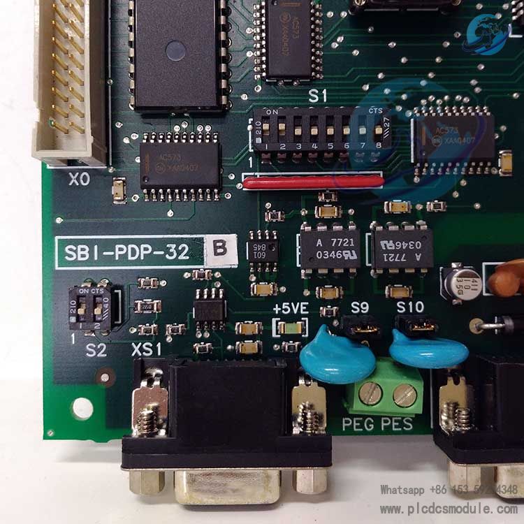
Switch Functions: The board is equipped with two DIP (Dual In-line Package) switches, S1 and S2. Among them, the S1 switch is used to set the slave address. Addresses "0" and "1" are dedicated to the host and cannot be occupied. In addition, the S1-8 switch has no impact on the address and must always be set to OFF. The board needs to be restarted for the address modification to take effect. The S2 switch is used to control the on/off of the bus termination resistor. The physical board at the end of the network must turn on this resistor, where ON indicates connection and OFF indicates disconnection.
Connection Ports: The bus cable is connected through the XS1 or XS2 connector. During installation, it is necessary to ensure that the bus connector is in the same direction as the terminal of the adjustment card. Meanwhile, when the board is working, the +5V and +5VE indicator lights will be on, and the DEA indicator light will be on when entering the data exchange phase, facilitating the staff to intuitively judge the operation status.
Core Functions and Application Scenarios
Core Functions: It is essentially a connection conversion component between the inverter and the Profibus-DP network, serving as a communication bridge between the drive and the industrial control main network. It enables the TPD32 series drives to access the Profibus-DP network, realizing collaborative control among devices.
Application Scenarios: It is suitable for various industrial automation scenarios such as power generation, automated production lines, and machine tool control. It is particularly well-suited for systems that require centralized management and control of multiple drives and sensors via the Profibus-DP bus, such as the cluster control of drive equipment in automobile assembly lines and the centralized transmission of sensor data in power equipment.
Customers who purchased this product are also browsing the following products:
NI PXI-7852R 8 AI channels I/O Module
ABB UCD224A102 3BHE023681R0102 controller Module
GE Multilin UR6AV DIGITAL I/O MODULE


 3005319639