Note; All products on this site are special products, the market price has been fluctuating, the specific customer service offer shall prevail, because the product is a new product, the picture is not a real shot, please confirm with customer service before placing an order model and product, price and other details, the site used, new are for sale, please contact customer service communication. The
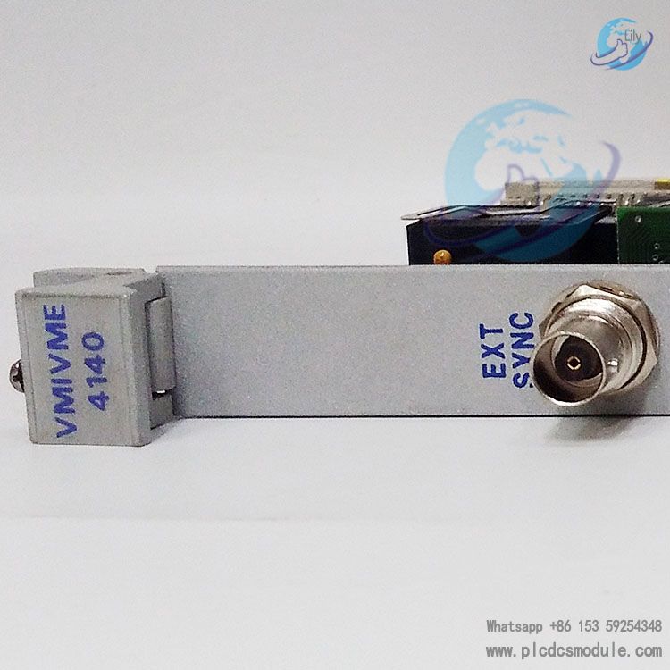
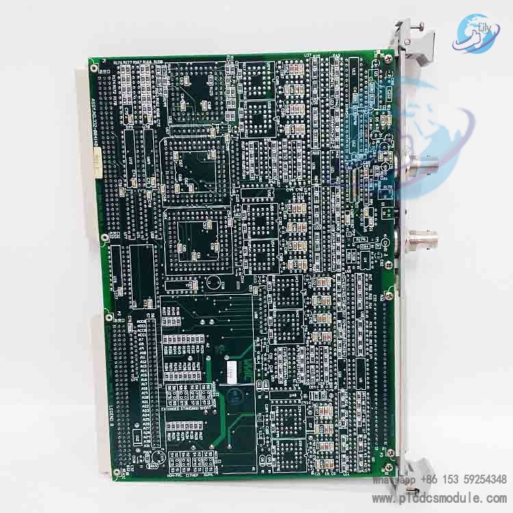
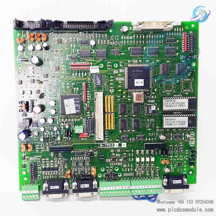
VMIVME-4140-001 is a high-performance 32-channel 12-bit analog
output board launched by VMIC (a subsidiary of GE Fanuc). Exclusively designed for VMEbus systems, it is suitable for scenarios with stringent requirements for analog signal output accuracy and channel density, such as industrial automation, test and measurement, and control systems.
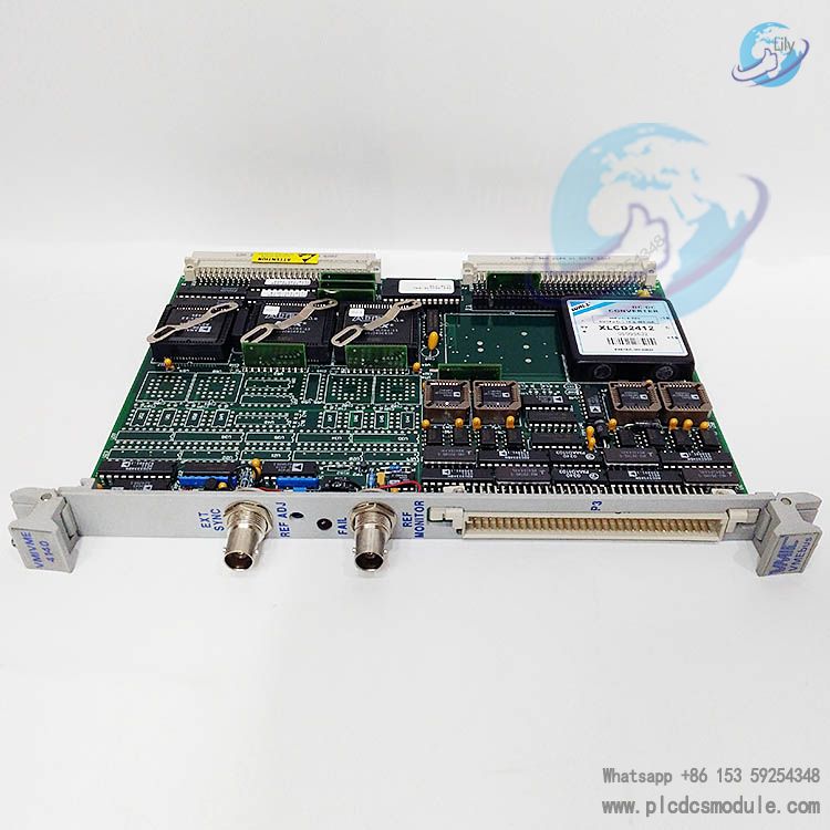
Equipped with independent Digital-to-Analog Converters (DACs), flexible voltage range configuration, automatic calibration and self-test functions, as well as reliable hardware protection design, this product can provide users with a stable and accurate multi-channel analog signal output solution. Meanwhile, it is compliant with VMEbus specifications, enabling easy integration into various industrial control systems.
related documents
 VMIC VMIVME4140 Manual.pdf
Technical Specifications & Key Features
Core Technical Specifications
Channel Configuration32 independent analog output channels, each equipped with a dedicated 12-bit DAC. Supports non-scanned random update or synchronous update (external trigger/software trigger).
Output PerformanceThe maximum output current per channel is up to 10mA, with a typical output impedance of 0.82Ω. It has short-circuit protection function and can withstand short circuits to ground or +15VDC.
Voltage RangeSoftware-selectable unipolar (0~2.5V, 0~5V, 0~10V) or bipolar (±2.5V, ±5V, ±10V) output, meeting signal requirements of different application scenarios.
Data FormatBipolar output supports 2's Complement or Offset Binary format; unipolar output adopts Straight Binary format. All data is right-aligned.
Interface SpecificationsCompliant with VMEbus Rev.C standard. Supports byte (D08 (EO))/word (D16) data access, as well as short address, standard address and extended address modes, plus privileged/unprivileged access modes.
Calibration & Self-TestBuilt-in 16-bit Analog-to-Digital Converter (ADC) and voltage reference. Supports system reset-triggered or software-triggered automatic calibration and full-channel self-test. Calibration coefficients are stored in RAM.
Key Features
Independent Channel DesignEach output channel is configured with a dedicated DAC, supporting independent inter-channel control to avoid cross-interference. It also supports synchronous update function, which can realize synchronous output of all channels via software commands or external TTL trigger signals.
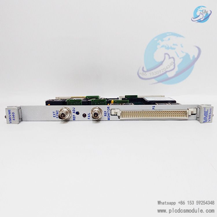
Flexible Calibration MechanismThe front panel is equipped with a BNC reference voltage monitoring interface and potentiometer adjustment knob, supporting users to manually calibrate the internal ±10VDC precision reference voltage with a calibration accuracy of up to ±0.001VDC.
Comprehensive Self-Test & DiagnosticsBuilt-in self-test network, realizing channel fault detection through analog multiplexer (MUX) and ADC. Fault status is stored in Self-Test Status Registers (SSRs), facilitating users to quickly locate faulty channels.
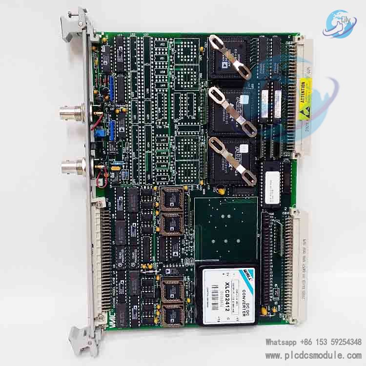
Hardware Protection & ReliabilityOutput channels are equipped with buffer protection circuits, which are defaulted to offline status during power-on and automatically disconnected from field wiring during calibration/self-test to avoid external interference. The 32-channel version adopts dual DC-DC converters for power supply, converting VMEbus 5V logic power into isolated and stable ±15VDC analog power to enhance anti-interference capability.
Easy Configuration & Maintenance29 jumpers are used to set base address, address mode and access mode, supporting flexible system integration. The front panel is provided with status LED indicators for intuitive display of board working status, as well as standard P2/P3 connectors for convenient field wiring and maintenance.
Hardware Architecture & Working Principle
(I) Core Hardware Modules
VMEbus Interface ModuleResponsible for communication and interaction with the VMEbus system, supporting functions such as register read/write and command transmission. It includes core control registers like the Board ID Register (BID) and Configuration Control Register (CCR). The BID register can identify the board model and channel configuration via the read value ($2A00 corresponds to 32 channels).
Digital Signal Processor (DSP)Serving as the core control unit, it is responsible for calibration algorithm execution, self-test logic control, DAC data correction, and other tasks. During calibration, it estimates the channel transfer function using the least square method, calculates and stores the gain and offset coefficients. During operation, it corrects the output value based on user data and calibration coefficients to ensure signal accuracy.
Analog Output ModuleConsists of 32 12-bit DACs, output buffers, and output switches. The DACs adopt a dual-data register design, enabling the write-trigger update mechanism. The output buffers provide short-circuit protection; in the offline state, the output impedance is as high as 10MΩ to prevent signal leakage.
Self-Test & Calibration ModuleComposed of a 16-bit ADC, analog multiplexer (MUX), voltage reference, and output monitor. During self-test, the MUX selects the target channel, the ADC collects the output signal and compares it with the theoretical value. If the deviation exceeds the threshold, the channel is marked as faulty.
Power Supply ModuleThe 32-channel version is equipped with two DC-DC converters, powering channels 0–15 and 16–31 respectively; the 16-channel version only requires one converter, ensuring the stability and isolation of the analog power supply.
(II) Working Process
- Power-On/Reset PhaseAfter the board is powered on or receives a software reset command, it automatically enters calibration/self-test mode, with all output channels set to offline. The DSP performs full-channel calibration, calculates and stores the gain and offset coefficients for each voltage range. After the self-test is passed, the BID register is updated to the corresponding channel configuration value ($2A00 for 32 channels), and the board enters the ready state.
Signal Output PhaseThe user writes output data to the output data register of the corresponding channel via the VMEbus. The DSP corrects the data using the channel’s calibration coefficients and sends it to the DAC. According to the synchronization configuration (asynchronous/software-synchronized/external-synchronized) in the CCR register, the DAC outputs the corresponding analog signal, which is transmitted to field devices through the P3 connector after passing through the buffer.
Self-Test & Calibration TriggeringUsers can trigger full-channel calibration/self-test or single-channel testing via software commands. During full-channel testing, all outputs are offline; during single-channel testing, only the target channel participates in the detection without affecting the normal operation of other channels. The test results are fed back through the Self-Test Status Registers (SSRs).
Typical Application Scenarios
Actuator drive signal output in industrial automation control systems
Multi-channel analog signal generation in test and measurement equipment
High-precision control systems in aerospace, defense electronics and other fields
Valve regulation, motor speed control and similar scenarios in process control
Customers who purchased this product are also browsing the following products:
GE IS200TTURH1CCC Mark VI printed circuit board
Honeywell FC-SCNT01 51454926-176 SC S300 CONTROLLER MODULE
ABB DASO120 57120001-EY Analog Output Board
GE IS200TRLYH1BGF Mark VI Relay Output Board


 3005319639