


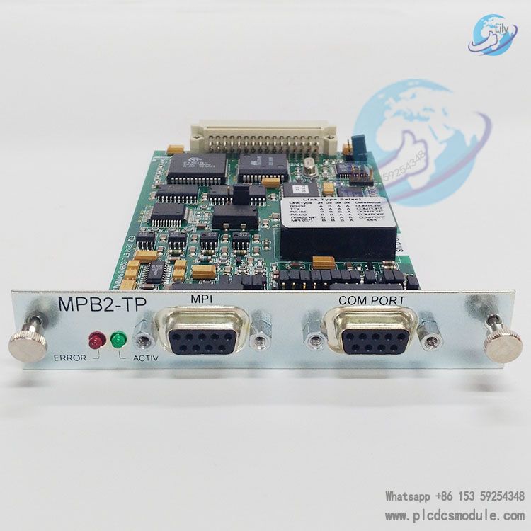
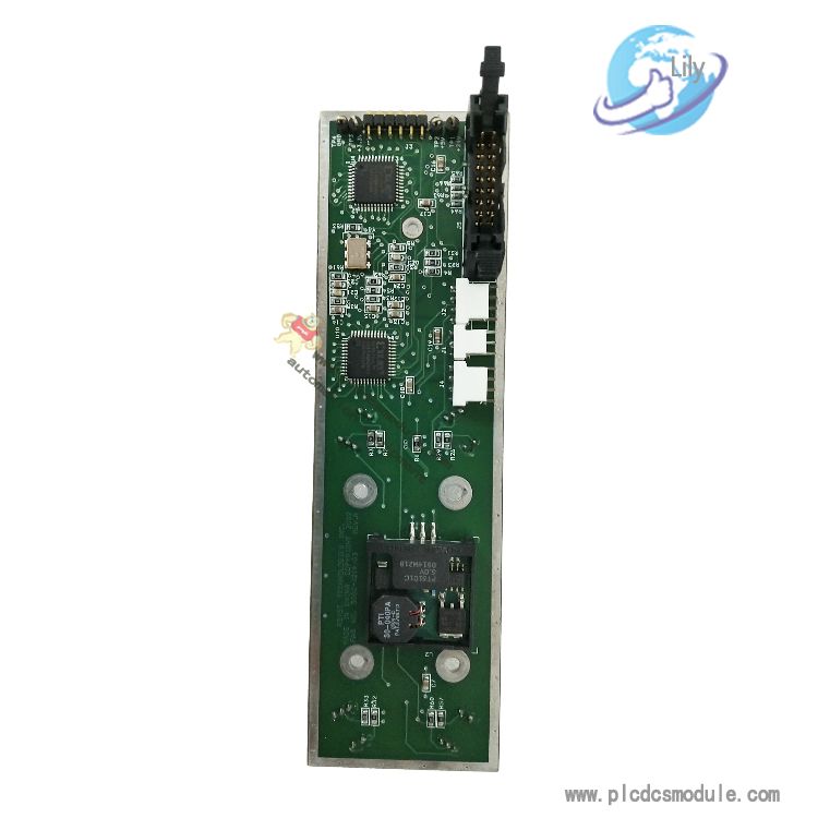
Eaton MPB2-TP is a high-performance communication module launched by Eaton Automation, specifically designed for MICRO PANEL (XV400) devices. It shares the same core functions as the MPB1-TP, with the additional integration of a dedicated MPI interface for SIMATIC S7. The module supports multiple physical interface protocols including RS232, TTY, RS422 and RS485, and is compatible with two types of drivers: BCI 1.0 and BCI 2.0. It can be adapted to PLCs from numerous brands such as Mitsubishi, Siemens and Omron, and is widely used in data transmission scenarios within industrial automation control systems.
Featuring firmware stored in flash memory, the module supports driver updates. It is equipped with comprehensive fault indication and bus protection functions, which can ensure the stability and reliability of communication in industrial environments.
related documents
Core Features
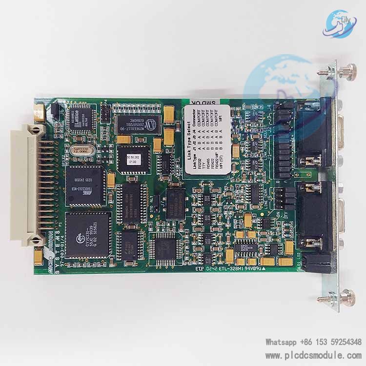
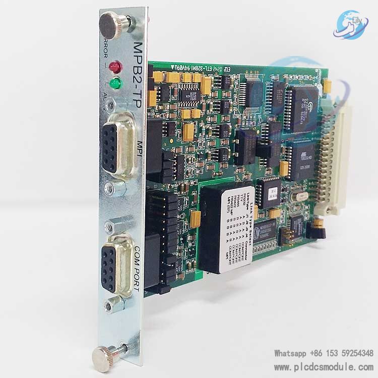
- Hardware Configuration and Interface DesignIt is equipped with dual interfaces: COM PORT and MPI. The COM PORT can be configured for RS232, TTY, RS422 or RS485 protocols via jumpers, while the MPI interface is exclusively designed for SIMATIC S7 and only supports RS485 configuration. Note that the two interfaces cannot be connected simultaneously.The front panel is fitted with two indicator lights: ERROR (red) and ACTIV (green). The ERROR light illuminates to indicate a failed data transmission in the last attempt and turns off upon successful transmission. The ACTIV light flashes briefly (approximately 50ms) during data transmission, providing intuitive feedback on the communication status.A built-in RS485/RS422 bus terminating resistor is included, which must be activated for network end nodes or point-to-point connections. This terminating resistor is not supported on the MPI interface.
- Firmware and Driver SupportThe firmware is stored in non-volatile flash memory. The latest standard driver (MPB.BIN) and alternative driver (SIMATIC S7 MPI driver: MPI.BIN) are pre-installed at the factory, and driver updates can be performed via serial port or MICRO PANEL devices.It supports jumper configuration for J6 (PRG/RUN) and J7 (STD/ALT). The PRG mode is used for loading new drivers, while the RUN mode allows switching between the standard driver and the alternative driver.The module is compatible with both BCI 1.0 and BCI 2.0 driver specifications. BCI 1.0 is suitable for basic data exchange, whereas BCI 2.0 supports more flexible multi-PLC data definition, covering multi-dimensional parameters such as station number, slot number and data format.
- Communication Capability and CompatibilityShielded cables with copper braided shielding layers must be used for communication, paired with metal or metal-plated connector housings. The shielding layer should be directly connected to the equipment housing to ensure electromagnetic compatibility (EMC).It supports the following maximum transmission distances for different interfaces: up to 15 meters at 19200 baud rate for RS232 protocol; up to 1200 meters at 100 kbps for RS422/485 protocol; and up to 1000 meters at 20 kbps for TTY protocol.The module is compatible with dozens of PLC models, including Siemens S7-31x/41x, Mitsubishi A/AX/FX series, Omron C-/H-/K series, etc., and supports various industrial protocols such as Modbus RTU, MPI and DF1.
Technical Parameters
It is applicable to the MICRO PANEL XV400 device. The interface types include COM PORT (supporting RS232/TTY/RS422/RS485 protocols) and MPI (supporting only the RS485 protocol and exclusively designed for SIMATIC S7). The compatible driver types are BCI 1.0 and BCI 2.0. The firmware is stored in non-volatile flash memory. It comes with a built-in RS485/RS422 terminating resistor (not supported by the MPI interface). The operating temperature complies with the working environment requirements of the MICRO PANEL device. It supports multiple protocols such as Modbus RTU, MPI, DF1 and Computer Link.
Installation and Configuration Guidelines
- Installation SpecificationsThe module may only be installed in the dedicated slot of the MICRO PANEL device (XV400). The device power supply must be turned off before installation or removal to prevent circuit damage.When connecting communication cables, follow the pinout definition specifications strictly. For the MPI interface, it is recommended to use original Profibus cables and connectors, and comply with Siemens MPI specifications in full regarding wiring length and installation requirements.
- Driver Loading Procedure
- Switch the J6 jumper to PRG mode, configure the COM PORT for RS232 protocol, and connect the PC serial port to the module COM PORT using a dedicated loading cable.Run the PC-side loading program (COMLOAD.EXE version 2.00 or higher), select to load either the standard firmware (S) or alternative firmware (A). After successful transmission, switch the J6 jumper back to RUN mode, and set J7 to STD or ALT according to requirements.After loading, verify the correctness of the driver version in the MICRO PANEL system interface.
- Commissioning and TroubleshootingDuring commissioning, first confirm the physical interface compatibility between the module and the PLC, then check whether the communication cable wiring complies with the wiring specifications of the corresponding PLC (approximately 60% of faults are caused by wiring issues).If the ERROR light remains on, troubleshoot for driver incompatibility, station address conflicts, or invalid data addresses. If none of the indicator lights illuminate, the selected driver may not be supported by the current firmware; contact technical support to obtain a newer version.In multi-node networks, ensure that the HSA (Highest System Address) is consistent across all devices (options: 15, 31, 63 or 126) to avoid station address duplication.
Customers who purchased this product are also browsing the following products:
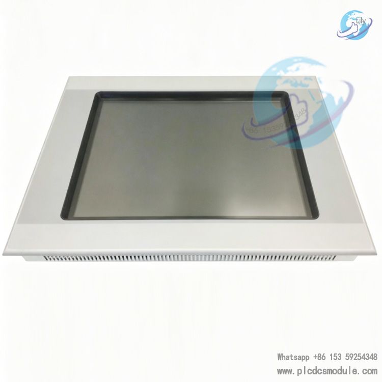
EATON XV-152-D6-84TVRC-10 HMI 8.4" TFT RESISTIVE TOUCH PANEL
GE General Electric IS200AEPAH1AHD Mark VI PCB Board
GE EPSCPE100-ABAC PACSystems RSTi-EP CPE100 Standalone Controller
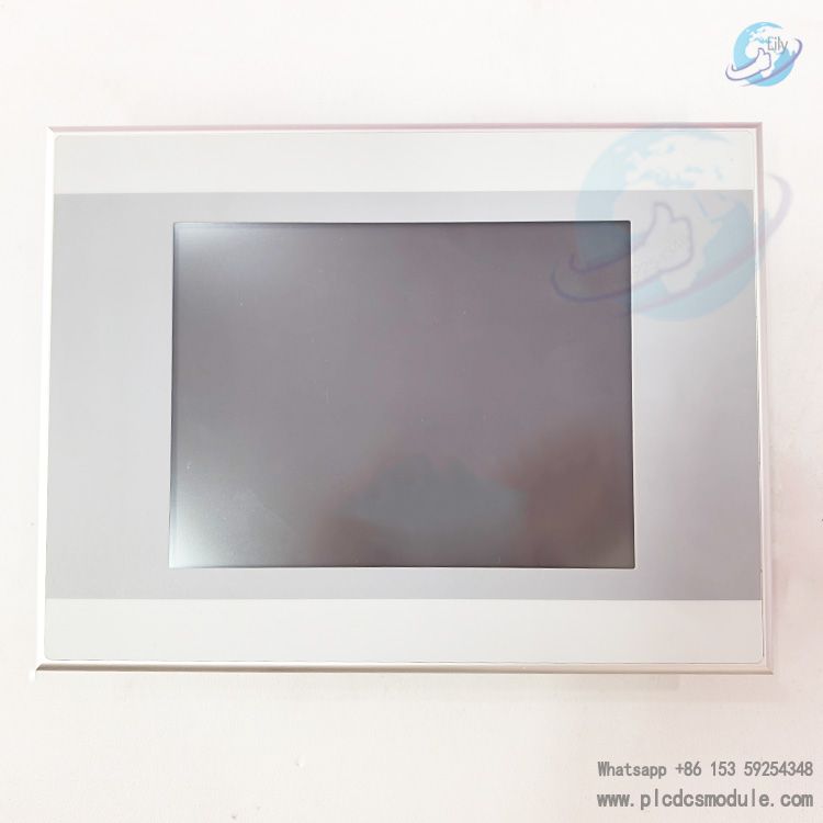
EATON XVS-440-10MPI-1-10 24 V DC Touch panel


 3005319639