


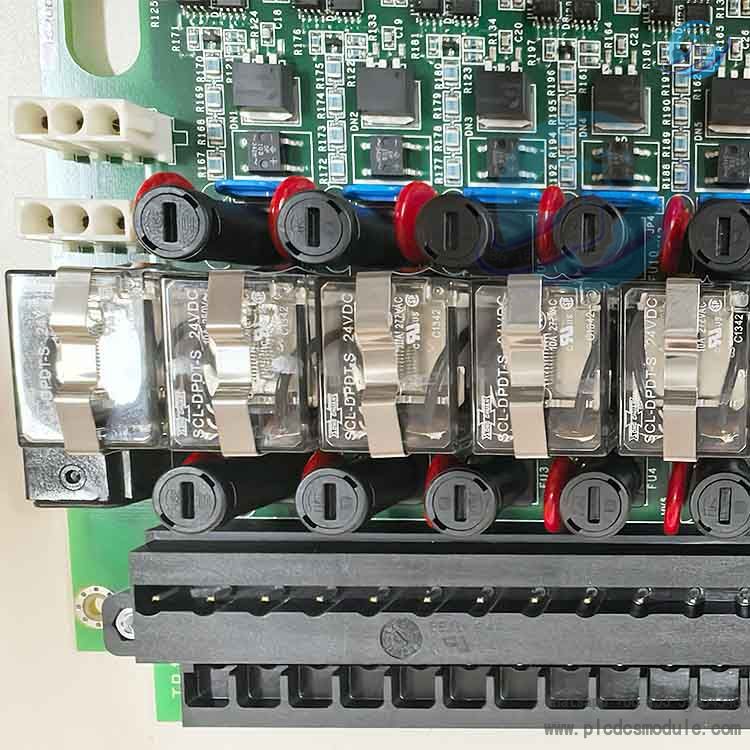

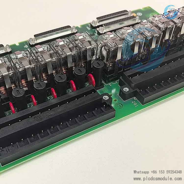
The GE IS200TRLYS1B is a triple modular redundant (TMR) relay output terminal board designed by General Electric (GE) specifically for the Mark VIe Speedtronic turbine control system. It is mainly used for safety tripping and critical actuator control in power generation and mechanical drive applications such as gas turbines and steam turbines. It integrates 12 Form C mechanical relays and 6 solenoid valve drive channels, with built-in 2-out-of-3 (2oo3) hardware voting logic to achieve fail-safe outputs. As a core I/O terminal component in the Mark VIe system, it ensures safe shutdown of the unit.

Core Technical Parameters
- Operating temperature: -20℃ ~ +70℃
- Storage temperature: -40℃ ~ +85℃
Humidity: 5% ~ 95% (non-condensing)Mounting: Standard Mark VIe I/O rack slot mountingProtection Class: Industrial IP20, suitable for harsh power plant environments

Key Features & Benefits
- Triple Modular Redundant Safety DesignHardware-based 2oo3 voting architecture prevents malfunctions caused by single-channel failures, meets SIL safety requirements, and completely eliminates single-point failure risks.
- Fail-Safe OutputsRelays are normally closed and open on loss of power, triggering safe unit shutdown in compliance with industrial safety standards.
- High-Reliability Industrial-Grade HardwareSealed mechanical relays with MOV surge suppression and freewheeling protection resist electromagnetic interference and voltage fluctuations in power plants, delivering long service life and high stability.
- Integrated Diagnostics & Status MonitoringBuilt-in coil continuity and impedance diagnostics enable real-time channel health monitoring via system software, supporting fast fault location.
- Modularity & CompatibilityStandard Mark VIe form factor, plug-and-play, seamlessly compatible with system backplanes and controllers. Supports multi-module expansion for units of various sizes.
- Multi-Scenario Drive CapabilitySupports both relay contact outputs and direct solenoid valve driving, covering critical applications including tripping, valve control, and interlock protection.
Installation & Maintenance
1. Installation Specifications
- EnvironmentInstall in standard Mark VIe I/O control cabinets, away from strong electromagnetic interference sources (variable frequency drives, power cables).
- Reserve ≥10 mm clearance for heat dissipation.Install cooling fans if ambient temperature exceeds 60℃.
- Mechanical InstallationWith system power off, insert the module into designated rack slots R1/R2/R3 and secure with latches to ensure full engagement with the backplane interface.For multiple modules, arrange in the sequence:Protection module → Trip terminal board → Actuator, with spacing ≥15 mm.
2. Wiring Guidelines
- Power
- 24VDC logic power: connect to V+/GND
- 125VDC trip circuit: connect to dedicated terminalsUse 2.5 mm² copper-core shielded cable with single-point grounding (ground resistance ≤ 4Ω).
- SignalsConnect PTUR/VTUR protection modules (command input), TTUR terminal board (status feedback), and trip solenoid valves (output) per terminal definitions.Solenoid cables: ≥1.5 mm² shielded cable.
- LoadsFor inductive loads (solenoid valves), connect freewheeling diodes or varistors in parallel to suppress back EMF.Do not exceed 2A per channel to avoid contact burning.

Recommended TRLY Series Relay Output Terminal Boards


 3005319639