


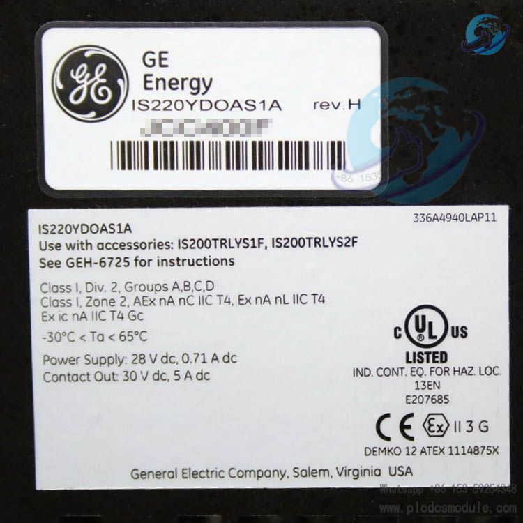
GE IS220YDOAS1A is a core discrete output I/O module for the Mark VIeSSafety Control System, designed specifically for hazardous locations (HazLoc). It is suitable for classified areas including Class I, Division 2, Groups A–D and Class I, Zone 2, Group IIC. Featuring high safety, reliability and compliance, it meets the safety control requirements for discrete signal output in industrial applications, and is widely used in critical safety loops such as turbine protection and process control.
The module carries rigorous classified location certifications and an intrinsic safety “ic” design, ensuring stable operation in potentially explosive atmospheres. It also supports flexible terminal board configurations to adapt to various load types and installation scenarios.
related documents
1. Core Product Features
1.1 Hazardous Location Compatibility
- Certifications & Compliance: UL E207685 certified, meeting US/Canadian Class I, Division 2 and Zone 2 standards, plus ATEX Zone 2, Group IIC certification (Certificate No.: UL DEMKO 12 ATEX 1114875X), complying with major global hazardous area regulations.
- Environmental Ratings: Pollution degree ≤ 2 (per EN 60664‑1); operating temperature range: -30°C to +65°C (-22°F to +149°F); suitable for installation in enclosures with IP54 protection.
- Safety Design: Built to intrinsic safety “ic” level. Relay contact outputs have independent safety parameter control to prevent explosion risks caused by circuit faults.
1.2 Hardware Configuration & Compatibility
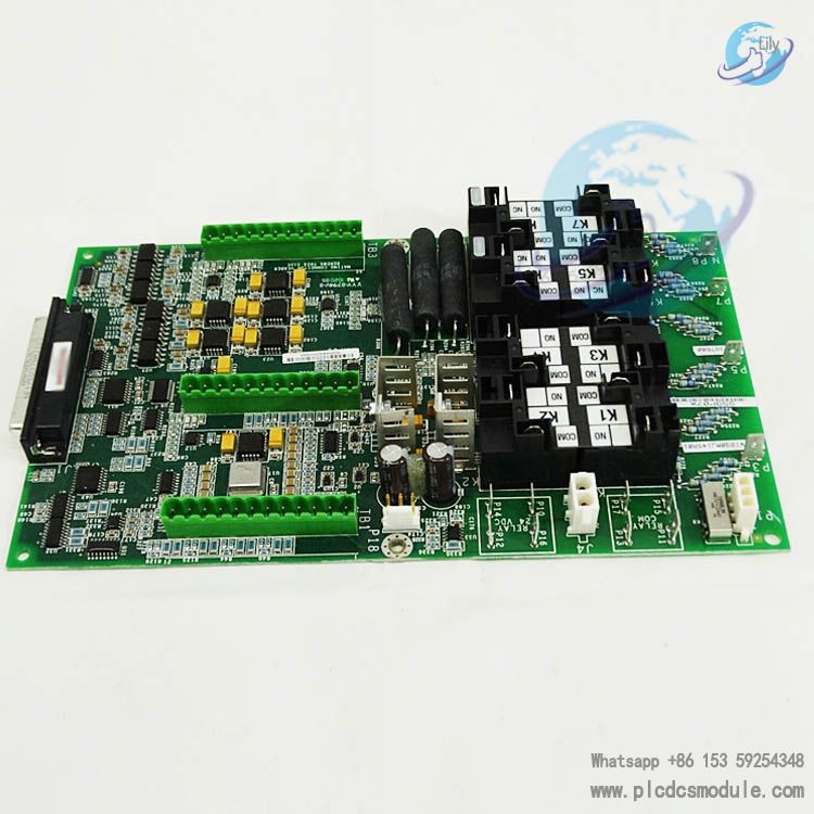
- Terminal Board Support: Only compatible with specific certified terminal boards:IS200TRLYS1F, IS200TRLYS2F, IS400TRLYS1F, IS400TRLYS2F.Terminal boards use barrier‑type terminal blocks, suitable for 22–12 AWG wire, with a screw torque of 9.6 in‑lb (1.1 Nm). Only copper conductors rated 90°C (194°F) or higher are allowed.
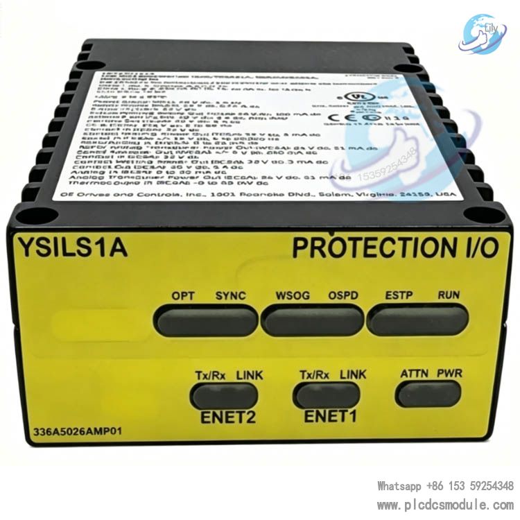
- Physical & Interface Characteristics: The module must be used with a Mark VIeS safety controller (e.g., IS420UCSCS2). Power and signals are transmitted via dedicated cabling; redundant power supply is supported to improve system availability.
2. Electrical Specifications
2.1 Power Parameters
- Supply Voltage: Min. 27.4 V dc, Nom. 28.0 V dc, Max. 28.6 V dc
- Max. Supply Current: 0.71 A dc
- Power input is provided via certified power distribution boards (e.g., JPDG, JPDS) with current limited to 3.5 A to meet hazardous area safety requirements.
2.2 Output Performance
- Contact Output (TRLYS1F, TRLYS2F terminal boards):Max. voltage: 30 V dc; Max. current: 5 A dc; suitable for resistive loads.
- Intrinsic Safety “ic” Parameters:Vmax = 30 V, Imax = 152 mA, Pi = 4.56 W, Ci = 0 μF, Li = 0 mH, ensuring compatibility with intrinsically safe apparatus.
Total Current Limit: Max. 13.5 A dc for JF1/JF2 interfaces; per‑channel output current adapts dynamically to load type (resistive/inductive).

3. Safety Design & Compliance
3.1 Intrinsic Safety Characteristics
- Circuit Protection: Current‑limiting and voltage‑limiting design achieves intrinsic safety “ic” protection. Cable capacitance (Ccable) and inductance (Lcable) must be strictly controlled, defaulting to Ccable = 60 pF/ft and Lcable = 0.2 μH/ft to ensure total system capacitance/inductance remains below safety thresholds.
- Installation Rules: The module must be installed in a tool‑removable enclosure with IP54 or higher. Wiring must comply with Class I Division 2 or Zone 2 wiring standards (ANSI/NFPA 70, IEC 60079‑25).
3.2 Certifications & Standards
- Classified Location Standards:ANSI/ISA‑12.12.01‑2015 (US/Canada);EN 60079‑0:2012, EN 60079‑11:2012, EN 60079‑15:2010 (ATEX).
- Device Markings: The product label includes hazardous area markings:
- US & CAN: Class I, Div 2, Groups A, B, C, D, T4
- ATEX Zone 2: Ex ic nA IIC T4 Gcalong with electrical ratings and temperature range.
4. Installation & Wiring Requirements
4.1 Wiring Specifications
- Conductor Requirements: Only copper conductors permitted.
- For ambient temperature ≤ 60°C (140°F): conductor rating ≥ 90°C (194°F)
- For ambient temperature > 60°C: conductor rating ≥ 105°C (221°F)
- Power & Signal Isolation: Contact wetting power must be connected via certified GE cables (e.g., 336A5026 series). In North America, UL‑listed fuses (≤3 A) or approved power supplies (Phoenix Contact QUINT‑PS series, Convertec TIS 150‑124) are required.
4.2 Terminal Board Wiring Details
- Relay Contact Terminals: Taking IS200TRLYS1F as an example, NO (normally open), COM (common), and NC (normally closed) terminals for relays K1–K12 correspond to specific positions (e.g., K1a = TB1.3, K1b = TB1.2, COM = TB1.2). Refer to the terminal board manual for exact definitions.
- Safety Precautions: De‑energize circuits before wiring or module replacement. Work only in non‑hazardous areas or when the area is confirmed safe. Do not replace non‑certified components.
5. Applications & System Integration
- Typical Applications: Emergency turbine shutdown, safety valve actuation in process industries, hazardous area equipment start/stop control, and other safety‑critical loops.
- System Integration: Can form a complete safety control system with Mark VIeS safety controllers, PPRA turbine protection modules, etc.
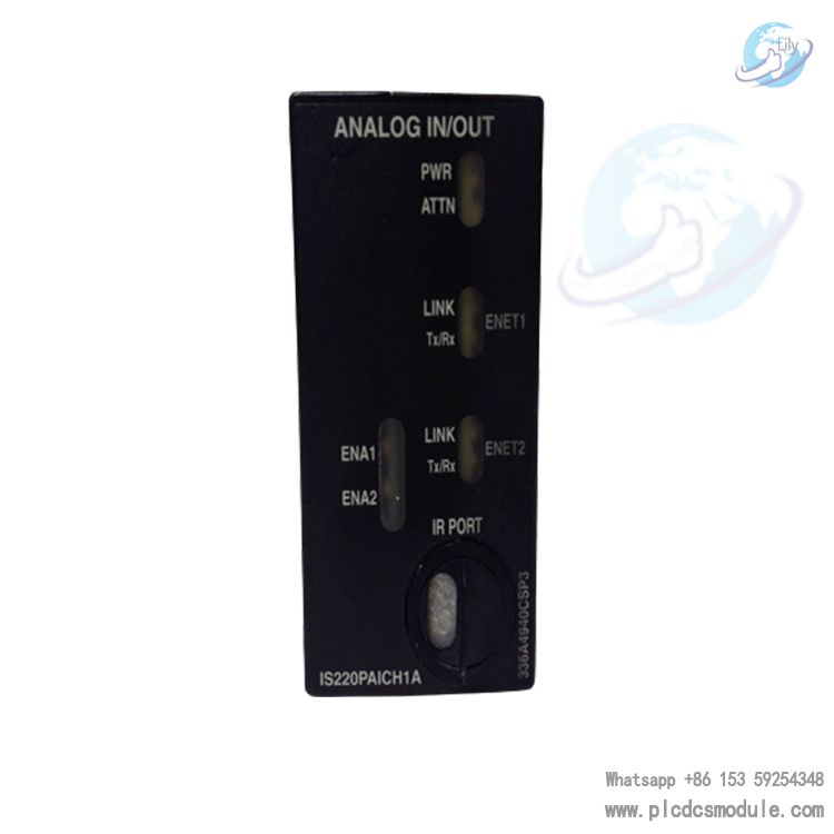
- Supports integration with ToolboxST software for configuration, status monitoring, and diagnostics. Compatible with Mark VIeS general‑market I/O modules including YAIC, YUAA, YVIB, etc.
6. Maintenance & Notes
- Routine Inspection: Regularly verify power stability, terminal board torque, and enclosure integrity to avoid safety risks from vibration or environmental corrosion.
- Troubleshooting: For abnormal output, first check load matching, cable length (max. 1000 ft), and intrinsic safety parameter compliance.
- Do NOT remove or insert the module or terminal board while powered.


 3005319639