


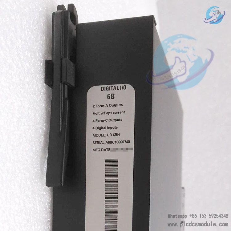
The GE UR6BH is a high-performance digital input/output (I/O) card for General Electric Multilin UR series relay systems. Designed for power system protection, control, and industrial automation, it serves as a core interface module for on-site digital signal acquisition and control command output.
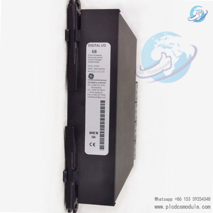
Featuring a 16-channel isolated digital I/O architecture compatible with the 24V DC industrial standard, the module delivers wide-temperature operation, high isolation voltage, and low power consumption. It seamlessly integrates with the full GE Multilin UR relay family (including T60, F60, C60, etc.), providing stable, reliable digital signal interaction for power substations, generator sets, industrial production lines, and other applications. Manufactured in the USA with industrial-grade hardware, it operates continuously and stably in extreme environments from -40°C to +85°C, supports hot swapping (in select configurations), and meets the high reliability and easy maintenance requirements of industrial field deployments.
Technical Specifications
| Parameter | Details |
|---|---|
| Model | UR6BH (GE Multilin UR Series) |
| Channel Configuration | 16 isolated digital I/O channels (configurable as input/output; default 8-in/8-out, or flexible 16-in/16-out switching) |
| Signal Type | Dry contact / active 24V DC input; transistor / relay output (24V DC, 0.5A per channel) |
| Operating Voltage | 24V DC (typical), compatible with 12–48V DC wide-range input |
| Power Consumption | ≤5W (full load) |
| Isolation Voltage | 2500V AC between channels; 1500V DC between channels and system ground |
| Operating Temperature | -40°C to +85°C |
| Storage Temperature | -55°C to +105°C |
| Humidity | 5%–95% (non-condensing) |
| Dimensions | 178mm × 100mm × 50mm |
| Weight | Approx. 1.0kg |
| Communication Interface | UR series relay internal bus; supports Modbus RTU/Modbus TCP (via main CPU forwarding) |
| Certifications | CE, UL, IEC 60255 industrial standards |
Key Features
1. High-Isolation Channel Design
All 16 digital channels are fully electrically isolated, effectively suppressing common-mode interference and surge voltages in industrial environments. This prevents external equipment faults from propagating to the control system, enhancing system anti-interference capability and operational stability.
2. Flexible I/O Configuration
Supports software-defined channel direction, allowing on-demand configuration as digital inputs (for monitoring switches, valves, limit signals) or digital outputs (for driving contactors, indicator lights, relays) to adapt to diverse control logic requirements.
3. Industrial-Grade Reliability
Engineered with wide-temperature, wide-voltage, and high-protection design, the module is fanless with no wearing parts, boasting an MTBF (Mean Time Between Failures) exceeding 1,000,000 hours. It meets the long-term operation demands of harsh working conditions in power, metallurgy, petrochemical, and other industries.
4. Seamless System Integration
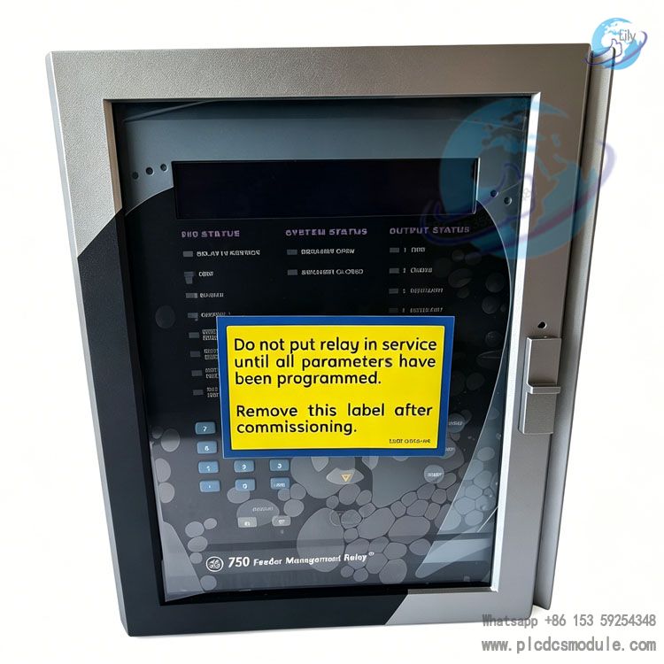
Exclusively compatible with GE Multilin UR series relays for plug-and-play operation, no additional drivers required. It works in coordination with UR series CPU, power supply, and analog I/O modules to build a complete protection and control system.
5. Real-Time Status Monitoring
Equipped with independent channel status indicators and a module operation indicator, it supports built-in fault self-checking (short circuit, overload, open circuit detection). Abnormal statuses are reported to the main system in real time for rapid fault location.
6. Low Power Consumption & Energy Efficiency
Full-load power consumption is below 5W, reducing system heat dissipation pressure, enabling dense cabinet installation, and lowering overall energy costs.
Installation & Maintenance
(I) Installation Steps
1. Pre-Installation Preparation
- Confirm system power is off (for non-hot-swap configurations).
- Inspect the UR6BH module for no damage and no bent pins.
- Prepare a screwdriver of the appropriate size, 24V DC power supply, and shielded signal cables (recommended 0.5–1.5mm²).
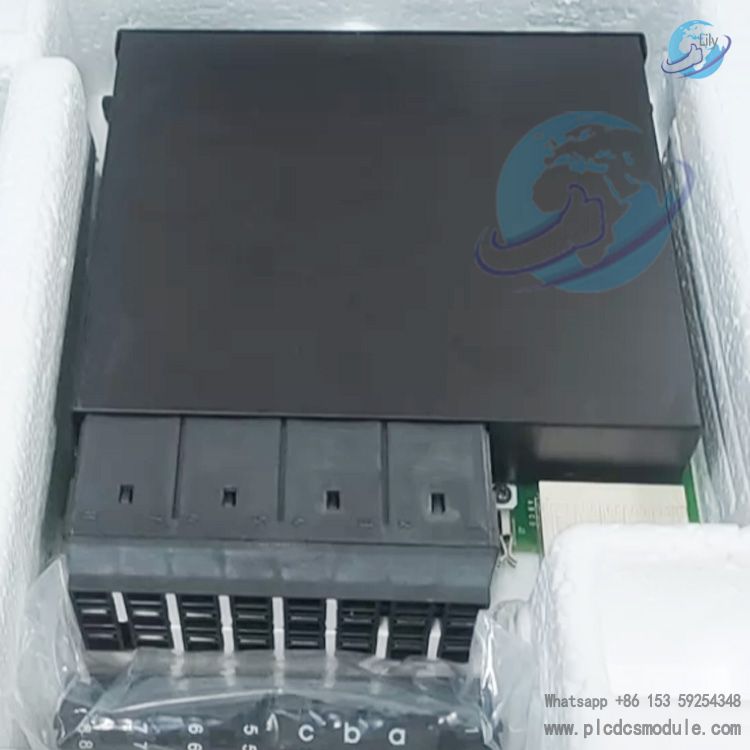
2. Hardware Installation
- Slide the module horizontally along the guide rail of the UR series relay rack, ensuring the latches are fully engaged and the module fits tightly to the rack without looseness.
- Connect the 24V DC operating power supply (observe correct polarity; power terminals feature foolproof design to prevent reverse connection).
- Digital I/O Wiring: Connect inputs to on-site dry contacts / 24V DC active signals, and outputs to external loads (contactors, indicator lights, etc.). Tighten terminals after wiring to ensure good contact, and ground the shield layer at one end.
3. Software Configuration
- After powering on the module, use UR series relay programming software (e.g., UR PC Software) to recognize the module.
- Configure channel direction (input/output), signal type, fault threshold, and other parameters, then download the configuration to the system to complete installation.
Maintenance Guidelines
1. Routine Inspection
- Check module indicator status weekly (steady operation light, channel lights flashing normally with signals) to confirm no abnormal alarms.
- Clean module surface dust monthly to prevent heat dissipation issues caused by dust accumulation.
2. Periodic Maintenance
- Tighten wiring terminals quarterly to prevent poor contact due to looseness.
- Test channel isolation performance and power supply stability annually, record operating parameters, and compare with standard values to identify potential hazards.
3. Troubleshooting
- No channel signal: Check wiring, power supply, and channel configuration; replace test signal cables to rule out external faults.
- Module unresponsive: Re-seat the module (power off operation), check rack bus connection; replace the module if the fault persists.
- Output overload: Inspect external loads for short circuit or overcurrent; replace with matching loads and reset the module.
4. Replacement & Storage
- Module replacement requires power-off operation (for non-hot-swap models); re-download configuration after replacement.
- Store idle modules in a dry, dust-free environment at -20°C to +60°C, avoiding moisture and impact.
Application Fields
1. Power Systems
- Substation circuit breaker and disconnector status monitoring and control
- Generator set protection system digital signal interaction
- Distribution line fault alarm and reclosing control
2. Industrial Automation
- Start/stop control, valve position feedback, and limit signal monitoring for metallurgical, petrochemical, and cement production lines
- Digital logic control and safety interlock systems for automated production lines
3. Energy & Infrastructure
- Grid-connected switch control for wind farms and photovoltaic power stations
- Gate and pump status monitoring and control for water conservancy hubs
- Rail transit signal systems and tunnel lighting control
4. Buildings & Public Facilities
- Digital I/O interaction for HVAC systems and fire alarm systems in large buildings
- Equipment status monitoring and remote control for intelligent power distribution rooms
Frequently Asked Questions (FAQ)
Q1: Does the UR6BH support hot swapping?A1: Hot swapping is only supported on high-end UR series relays (e.g., T60, F60) with hot-swap capability. For basic UR relay models, installation/removal requires power-off to avoid damaging the module and system bus.
Q2: What is the maximum number of input/output channels configurable?A2: All 16 channels are fully configurable. They can be set to 16-in/0-out, 0-in/16-out, or any mixed ratio (e.g., 8-in/8-out, 12-in/4-out) via one-click software configuration.
Q3: What is the maximum load capacity of output channels?A3: The maximum output current per channel is 0.5A (24V DC), supporting 12W per channel for resistive loads. For inductive loads, a freewheeling diode must be connected in parallel to prevent back EMF from damaging the module.
Q4: What is the difference between UR6BH and UR6TH?A4: UR6BH is a 16-channel isolated digital I/O module, dedicated to 24V DC, with a wide temperature range of -40°C to +85°C. UR6TH is an 8-in/4-out non-fully isolated module, compatible with 24–250V AC/DC, with a temperature range of -40°C to +70°C, suitable for low-power scenarios.
Q5: How to quickly troubleshoot module faults?A5: Step 1: Check the power indicator and operation light. Step 2: Verify channel configuration and wiring. Step 3: Replace with a spare module for testing to determine if the fault is in the module or external equipment.
Q6: Does it support third-party control systems (non-GE UR series)?A6: Direct connection to third-party PLC/DCS is not supported. Protocol conversion via a Modbus gateway or signal isolation converter is required for communication with third-party systems.
Q7: What is the service life of the module?A7: Under normal industrial conditions, the designed service life is ≥15 years. Regular maintenance and standardized wiring can extend service life, and avoiding harsh conditions such as moisture, corrosion, and overload can significantly reduce failure rates.


 3005319639