


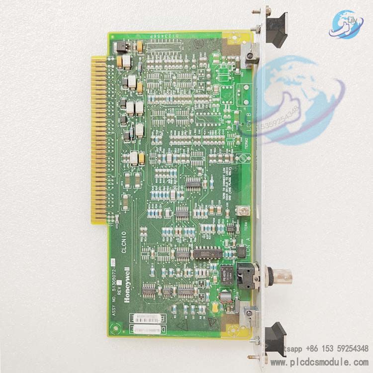
Honeywell 51305072-200 is a dedicated LCN I/O interface board (CLCN‑A/B EC compatible) designed for the Honeywell TDC 3000X system. As a core communication I/O paddle board for the Local Control Network (LCN), it is used for LCN node address configuration of 5‑slot / 10‑slot modules, dual coaxial communication link A/B interfacing, and shielding grounding. It complies with EU CE EMC and safety directives, supports software version R500 and above, and serves as critical hardware for system modules to access the LCN and achieve stable redundant communication.
Download
Basic Information
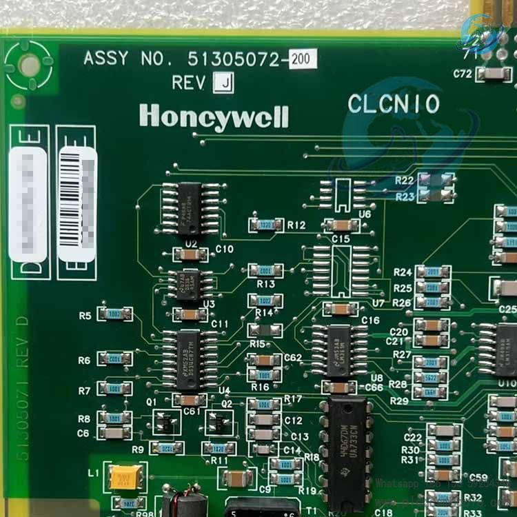
Part Number: 51305072-200Official Name: CLCN‑A/B LCN I/O Board (EC/CE Compliant)System: TDC 3000X Distributed Control SystemCompatibility: Supports TDC 3000X R500 software and CE‑compliant hardwareBoard Type: LCN I/O paddle board (mounted in rear I/O slots)Replacement: EC‑compliant version, replaces legacy LCN I/O boards (KLCN‑CA/KLCN‑CB)
Key Functions & Features
LCN Dual Redundant Communication
Provides dual LCN coaxial A/B link interfaces, supports redundant transmission to ensure high‑reliability communication, and adapts to LCN node networking for 5‑slot / 10‑slot modules.
Node Address Hardware Configuration
Onboard address jumper group supports binary setting of LCN node addresses 1–64 with parity check, ensuring unique and non‑conflicting addresses.
CE‑Compliant Grounding Design
Uses screw‑mounted I/O panel for reliable grounding of the panel and cable shield, meeting EU EMC and safety directives, and complying with EU market equipment requirements after 1996.
Wide Module Compatibility
Compatible with full series 5‑slot / 10‑slot configurations including Application Module (AM), History Module (HM), Gateways (CG/HG/PLCG), Universal Stations (US/UXS), etc.
No Field‑Adjustable Parameters
Only node address configuration required; no potentiometers or adjustable components, reducing on‑site maintenance complexity.
Hardware Specifications & Installation Notes
1. Physical & Installation
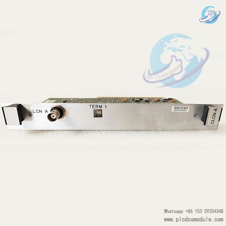
Mounting Location: Rear I/O slot of the module, corresponding to front functional board slot 2Fixing Method: Screw fastening (CE version), enhanced grounding and shieldingInterface Type: LCN coaxial A/B interfaces, T‑connector cascade connectionChassis Compatibility: Honeywell standard 19‑inch rack cabinet
2. Address Configuration Rules
Address Range: LCN nodes 1–64, assigned sequentiallyJumper Logic: Jumper removed = "1"; total number of removed jumpers (including parity bit) is oddCooperation Rule: When used with K2LCN/K4LCN, address is configured only on this board; no address jumpers on processor board.
3. Compatible Replacement Models
51305072-100 (CLCN‑A/B EC), 51305072-400 (CLCN‑A/B)51305072-700 (CLCN‑A/B EC), same‑series A/B end plates (-200/-300/-500/-600/-800/-900)
Applications
- LCN network access for 5‑slot / 10‑slot modules in TDC 3000X systems
- System expansion / retrofitting in EU regions requiring CE compliance
- LCN interface replacement for application modules, gateways, history modules, and operator stations
- LCN I/O communication supporting K2LCN / K4LCN processor boards
Maintenance & Fault Diagnosis
Normal Status
- Module passes power‑on self‑test, green PASS LED remains steady on
- Node address displays normally, LCN communication uninterrupted
- Coaxial A/B link indicators blink normally
Abnormal Performance
- Red SELF TST/ERR LED remains steady on
- Failure to go online, node address not displayed
- LCN bus errors, communication interruption
Troubleshooting Steps
- Power off and check board fastening, coaxial connections, and grounding
- Verify node address jumpers to ensure uniqueness and correct parity
- Replace with an identical board to verify hardware failure
- Check status of backplane and front‑end processor boards (K2LCN/K4LCN)
Frequently Asked Questions (FAQ)
What is the core difference between 51305072-200 and standard LCN I/O boards?It is a CE/EC compliant version with screw-mounted enhanced shielding and grounding, meeting EU safety and EMC requirements. It replaces legacy LCN I/O boards, supports dual A/B links, and is compatible with R500 systems.
Must this board be used with K2LCN/K4LCN?No. It can work with processors such as EMPU, HMPU, HPK2, K2LCN, K4LCN, etc. Only when used with K2LCN/K4LCN does the address need to be set on this board only.
What happens if the LCN node address is set incorrectly?It will cause address conflicts, failure to go online, bus errors, and module initialization failure. The address must be unique, within 1–64, and have correct parity.
Can it directly replace 51305072-100/-400/-700?Yes, all CLCN‑A/B models in the same series are functionally compatible. When replacing, copy the address jumper settings to ensure consistent configuration.
What safety precautions should be taken when replacing this board?Always perform operations with the module fully powered off; use ESD anti-static protection; verify coaxial A/B interfaces are not reversed; only configure the address and do not modify other jumpers.
Which modules cannot use this board?Modules equipped with Clock Source/Repeater (CS/R) boards cannot use it, as this may damage the backplane and modules. Redundant AM modules require HMPU, and mixed use with some processor combinations is not recommended.


 3005319639