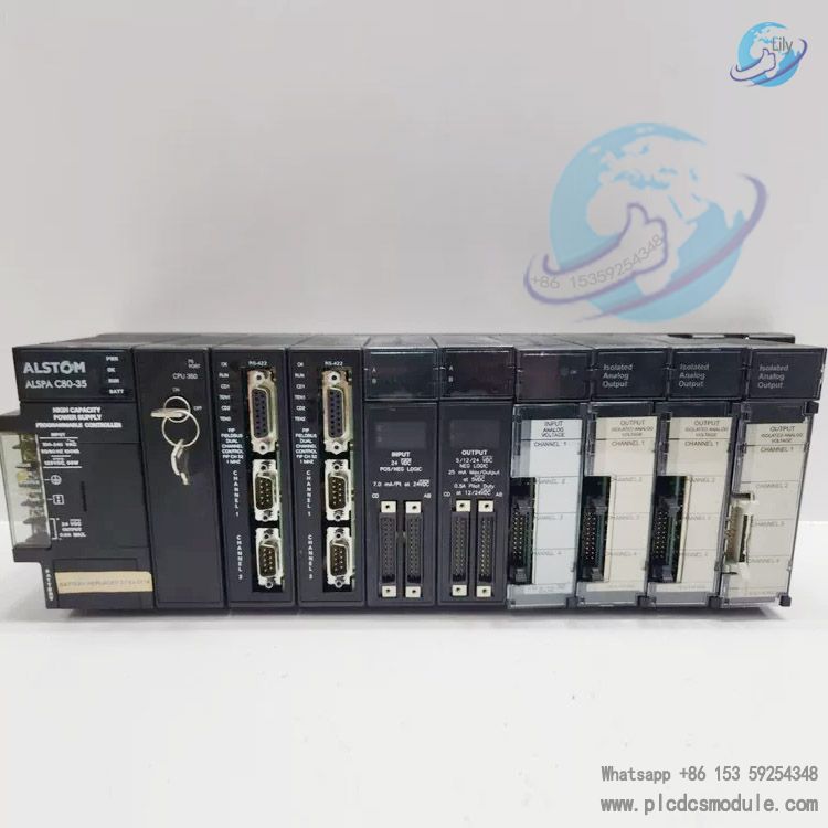
ALSTOM ALSPA C80-35 CPU 350 Fieldbus Dual-Channel Control I/O Analog Voltage Module
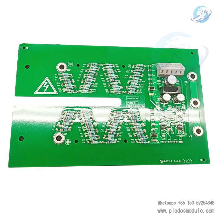
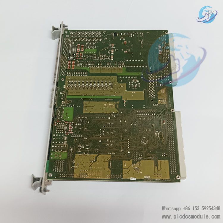
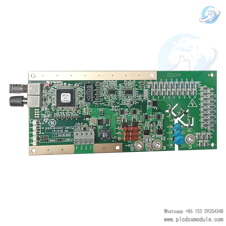
The ALSTOM ALSPA C80-35 CPU 350 Fieldbus Dual-Channel Control I/O Analog Voltage Module is a core component of Alstom’s ALSPA C80-35 series PLC control system. Designed specifically for high-precision analog voltage signal acquisition, dual-channel fieldbus communication, and real-time control in industrial automation scenarios, it features high stability, strong compatibility, and redundant communication capabilities, making it widely suitable for harsh industrial environments such as power, energy, and manufacturing.
Specifications
- Product Positioning: Dedicated analog voltage I/O module for the ALSPA C80-35 PLC system, integrating dual-channel fieldbus interfaces and control functions
- Channel Characteristics: Dual independent analog voltage input/output, supporting single-ended/differential signal connection
- Voltage Ranges
- Input: ±10V, 0–5V, 0–10V (software configurable)
- Output: ±10V, 0–5V, 0–10V (software configurable)
- Resolution: 12-bit or 16-bit (depending on hardware version), typical accuracy ±0.1% of full scale
- Fieldbus: Dual independent FIP (WorldFIP) fieldbus interfaces, supporting redundant communication
- Communication Rate: 1 Mbps / 500 kbps / 125 kbps (configurable)
- Power Supply: 24 VDC (operating range 18–30 VDC), typical power consumption 5W
- Electrical Isolation: Galvanic isolation between channels and between channels and the system, isolation voltage ≥1500Vrms
- Physical Characteristics
- Dimensions: Standard C80-35 PLC module form factor, compatible with IC693 series bases
- Operating Temperature: 0–60℃; Storage Temperature: -40℃ to 85℃
- Protection: Industrial-grade PCB coating, vibration and interference resistant
- Certifications: CE, UL 508, Class I Div 2 Groups ABCD, suitable for hazardous locations
II. Functional Advantages
- Dual-Channel Redundant CommunicationDual independent FIP bus channels support hot standby redundancy; a single channel failure does not disrupt system operation, ensuring continuous communication.
- High-Precision Analog Signal ProcessingHigh-resolution ADC/DAC with low noise and low drift design enables accurate voltage signal acquisition/output, ideal for precision control loops.
- Flexible Configuration & CompatibilitySoftware-programmable ranges, filtering parameters, and communication addresses; fully compatible with GE Fanuc 90-30 series hardware and bases.
- Real-Time Control & DiagnosticsBuilt-in real-time I/O scanning, fault diagnosis, and status feedback, supporting wire break detection, over-range alarms, and communication status monitoring.
- Industrial-Grade ReliabilityWide temperature range, isolation, and anti-interference design with an MTBF exceeding 200,000 hours, suitable for continuous production in power, metallurgy, chemical, and other industries.
Application Scenarios
- Power Systems: Excitation control for generator sets, substation voltage monitoring, grid analog acquisition and regulation
- Process Control: Closed-loop control of pressure, flow, and level analog signals in chemical/pharmaceutical processes
- Manufacturing: Servo control, tension control, and precision positioning voltage feedback on automated production lines
- Energy & Metallurgy: Analog control and fieldbus distributed I/O communication for blast furnaces and rolling mills
IV. Installation & Maintenance Guidelines
- Installation: Insert into the standard C80-35 base and ensure secure locking; configure bus termination resistors as required
- Wiring: Use shielded twisted-pair cables for analog signals with single-ended grounding of the shield; separate power and signal wiring
- Configuration: Set ranges, addresses, and communication parameters via P80-Workbench or Logicmaster 90 software
- Maintenance: Regularly inspect terminal connections and module status indicators; troubleshoot by verifying configurations, calibrating signals, and replacing modules if faulty
Frequently Asked Questions (FAQ)
Q1: The status indicator does not light up after power-on. How to troubleshoot?A1: 1. Verify normal 24VDC power supply and correct polarity; 2. Confirm power supply to the base slot is intact; 3. Reinsert the module to check for poor contact; 4. Test in an alternate base slot to rule out base failure.
Q2: What to do if analog voltage input readings are inaccurate or highly fluctuating?A2: 1. Ensure the configured range matches the actual signal; 2. Check signal cable shielding and grounding to reduce electromagnetic interference; 3. Enable software filtering and extend filtering time; 4. Calibrate the module or test with a replacement signal source.
Q3: How to resolve abnormal or interrupted dual-channel FIP bus communication?A3: 1. Verify bus address, rate, and termination resistor configurations; 2. Inspect bus cables, connectors, and shielding; 3. Switch to the redundant channel to identify single-channel faults; 4. Update bus firmware and restart the module and controller.
Q4: Is the module fully compatible with GE 90-30 PLCs?A4: Hardware bases, dimensions, and electrical interfaces are fully compatible; however, Alstom-specific FIP bus functions must be configured using Alstom P80-Workbench, as GE software does not support FIP setup.
Q5: How to identify the cause when the FAULT indicator illuminates?A5: 1. Read fault codes (wire break, over-range, communication error, hardware fault) via programming software; 2. Inspect input/output loop wiring; 3. Restore factory settings and re-download parameters; 4. For hardware faults, return for repair or replace the module.
Q6: Is hot swapping supported? What precautions apply during replacement?A6: The C80-35 system supports module hot swapping. Before replacement, label wiring and configurations; the new module must be the same model with identical settings. It will be automatically recognized upon insertion without system restart.
Q7: How to fix no analog output signal or abnormal voltage?A7: 1. Confirm output configuration, range, and enable status; 2. Check load matching and open circuits in the loop; 3. Perform software forced output testing to distinguish between module and program issues; 4. Calibrate the output or replace the module.