


The Multilin UR8FH is a high-performance CT/VT (Current/Voltage Transformer) input module under the Multilin UR series of GE Vernova (formerly General Electric). Serving as a core expansion component for Multilin UR series universal relays, it is engineered for high-precision signal acquisition and protection control in power systems. The module can be directly connected to standard CT/PT secondary circuits without external transmitters. Widely applicable to critical scenarios such as medium and high-voltage substations, power plants, and industrial power systems, it acts as the core hardware for implementing differential protection, impedance protection and power quality monitoring.
Product Advantages
High-precision Acquisition Ensures Protection ReliabilityEquipped with an 18-bit Σ-Δ ADC, it adopts hardware-level synchronous sampling across all channels at ≥4kHz. It achieves amplitude accuracy of ±0.2% and phase error less than 0.5° at 50/60Hz, accurately capturing the amplitude and phase of power frequency signals and avoiding misoperation of differential protection.Native Direct CT/PT Connection Simplifies System ArchitectureSupports direct connection of 1A/5A CTs and 100V/120V PTs with no additional signal conversion equipment required. It reduces hardware costs and wiring complexity, and is compatible with single-phase, three-phase and three-winding device wiring.Industrial-Grade Reliability for Harsh EnvironmentsBuilt with industrial-grade electronic components, it operates stably from -40°C to +85°C. It adapts to industrial sites with wide temperature fluctuations, high humidity and strong electromagnetic interference, with an MTBF (Mean Time Between Failures) of over 100,000 hours.Modular Plug-in Design for Easy Maintenance and ExpansionFeatures standard slot-mounted installation and hot-swap support, allowing module replacement without system shutdown. It is compatible with UR series main devices such as T60, G60 and B90, enabling flexible expansion of I/O and acquisition channels on demand.
Technical Parameters
| Parameter Category | Specifications |
|---|---|
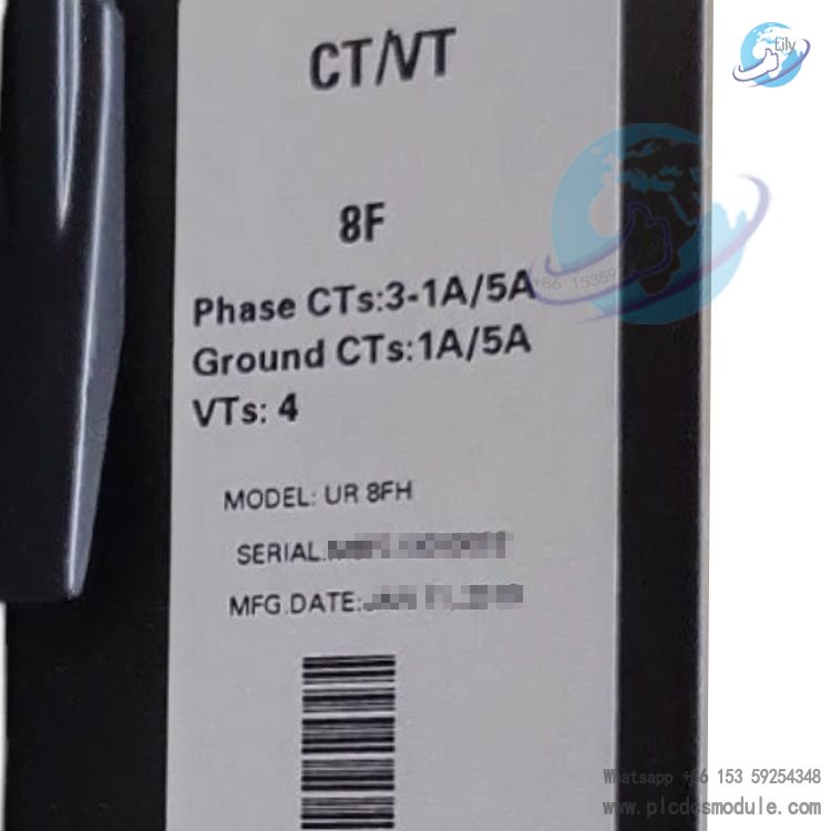
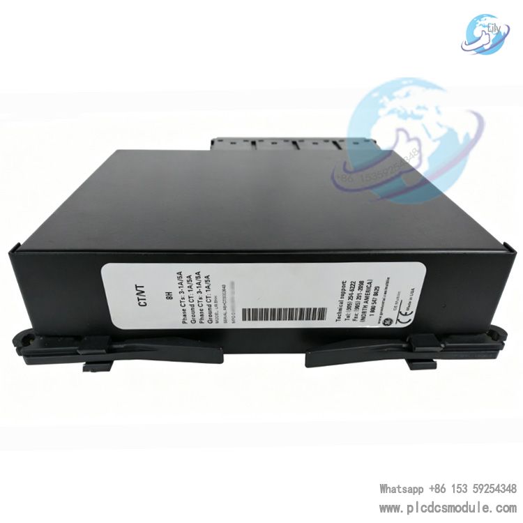
| Module Type | CT/VT Input Module (8 channels: 4 CT + 4 VT) |
| CT Input | Rated 1A/5A; supports 3-phase current + 1 ground current |
| VT Input | Rated 100V/120V; 4-channel voltage acquisition |
| Sampling Accuracy | Amplitude ±0.2%, Phase < 0.5° (50/60Hz) |
| Sampling Rate | ≥4kHz, full-channel hardware synchronization |
| Operating Voltage | 24V DC / 48V DC (±10%) |
| Power Consumption | <10W |
| Operating Temperature | -40°C ~ +85°C |
| Storage Temperature | -40°C ~ +85°C |
| Relative Humidity | 5%~95% (non-condensing) |
| Dimensions | 110mm×22.5mm×105mm |
| Weight | 250g |
| Communication Protocol | IEC 61850, Modbus RTU, DNP3 |
| Compatible Main Units | UR series: T60 (Transformer Protection), G60 (Generator Protection), B90 (Busbar Protection), etc. |
Core Functions & Features
High-Precision Power Signal Acquisition
Function:8-channel synchronous acquisition of three-phase current, three-phase voltage and ground current; outputs real-time effective value, phase and frequency data.Application Scenarios:220kV/500kV hub substations, providing three-side current/voltage signals for transformer protection relays; combined-cycle power plants, collecting generator terminal CT/PT signals to support differential protection and loss-of-excitation protection.
Support for Multiple Types of Power Protection
Function:Compatible with differential protection (87), impedance protection (21), overexcitation protection (24), ground fault protection, etc., with flexible protection logic configuration available.Application Scenarios:Pumped storage power stations, monitoring current distribution of hydro-generator sets to realize stator ground protection; high-voltage motors in industrial plants, providing overload, short-circuit and ground fault protection.
Power Quality Monitoring and Analysis
Function:Real-time monitoring of harmonics, three-phase unbalance and power factor; records power quality events and supports data uploading to SCADA system.Application Scenarios:Power quality sensitive sites such as semiconductor factories and data centers; monitors voltage sag and harmonic distortion to ensure stable operation of precision equipment.
Flexible Channel Configuration and Expansion
Function:Any channel can be configured as current or voltage input; multi-module cascading is supported to expand acquisition channels, adapting to complex primary equipment wiring.Application Scenarios:Protection for three-winding transformers and autotransformers; a single module meets multi-side signal acquisition without additional extension cabinets.
Fault Diagnosis and Alarm
Function:Real-time detection of CT open circuit, PT short circuit, reverse polarity and other faults; triggers alarms and records event logs, supporting remote diagnosis.Application Scenarios:Unattended substations; early warning of wiring faults to avoid protection mal-operation / refusal-to-operate and reduce operation and maintenance costs.
User Guide
1. Installation Procedures
Environment Preparation
Hardware Installation
Wiring Verification
2. Software Configuration
Device Connection
Channel Configuration
Protection Logic Configuration
Configuration Upload & Verification
3. Routine Maintenance
- Regularly check channel real-time vector diagrams and differential current calculation results via EnerVista to identify abnormal data.
- Inspect terminal tightness and cable insulation condition quarterly, and clean dust on the module.
- In case of CT Open or Phase Reversal alarms, power off immediately and inspect wiring polarity and circuit integrity.
FAQ


 3005319639