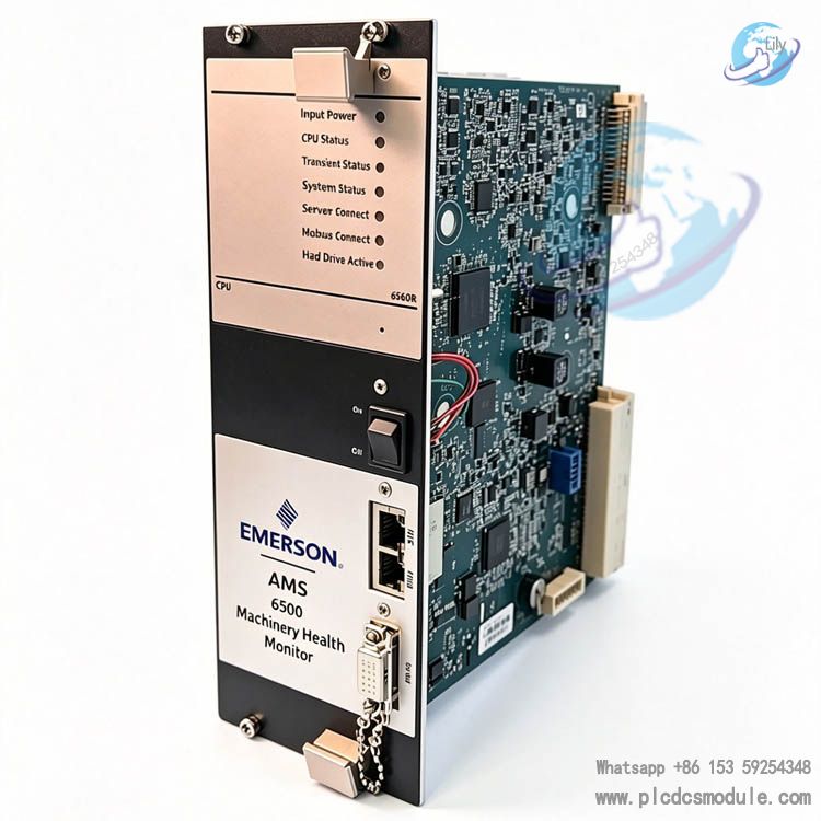
Note; All products on this site are special products, the market price has been fluctuating, the specific customer service offer shall prevail, because the product is a new product, the picture is not a real shot, please confirm with customer service before placing an order model and product, price and other details, the site used, new are for sale, please contact customer service communication. Emerson A6560R (Part No. D25625) serves as the core CPU processing board for the Emerson AMS6500 (CSi6500) online predictive machinery health monitoring system, engineered exclusively for online predictive vibration monitoring of rotating equipment. A transient data acquisition variant designated A6560RT was developed on the identical hardware platform.
Integrated with an FPGA and real-time signal processor, this board pairs with the A6510 analog input daughterboard. A single board accommodates 12 or 24 analog vibration channels alongside 2 to 4 tachometer speed pickup channels, enabling on-site high-speed spectral computation, bearing fault diagnostics, order tracking and PeakVue envelope analysis locally. Onboard alarm logic can be executed independently without reliance on a host PC.
Featuring multi-protocol connectivity via Modbus TCP, dual-port Ethernet and RS232 interfaces, it facilitates data interconnection with distributed control systems (DCS) and the AMS Machinery Manager host software. As the primary controller for online condition monitoring systems deployed on critical rotating machinery across petrochemical, power generation and metallurgical industries, D25625 is the original OEM ordering part number compatible with all standard AMS6500 rack assemblies.
DOCUMENT DOWNLOAD
 Emerson A6560R.pdf
Specific Specifications
(I) Hardware Channel Specifications
Analog Channels: 12/24CH (configured with 1 or 2 pieces of A6510 acquisition daughterboards)Tachometer Channels: 2 to 4 channels; input voltage: 0.5~24 V, input frequency: 0.1~2 kHz (max divided frequency 60 kHz limited to ≤2 kHz)Relay Channels: 2~4 SPDT dry-contact relays rated 24 VDC @ 0.5 A; 1 dedicated rack fault relay for power loss or restart alarmADC Performance: 24-bit analog-to-digital conversion with 95 dB dynamic range; 16-bit resolution for DC measurementSampling Performance: Max upper cutoff frequency up to 40 kHz, sampling rate at 102.4 k sps; synchronous scanning for DC and AC channels; full-channel RMS and peak-to-peak value scanning completed every 500 ms
(II) Accuracy & Algorithm Configuration
Accuracy Parameters
Crystal reference frequency tolerance: 0.01%; total harmonic distortion (THD): -90 dB; phase error ≤4° within 1~1000 Hz, ≤5° above 1000 Hz.Amplitude accuracy tolerance: 5% for 0.2~0.5 Hz, 2% for 0.5~25 Hz, 4% for frequencies over 25 Hz.
Spectrum Configuration
Spectral line resolution (LOR): selectable from 100 to 6400 lines; supports synchronous high-speed dual-channel acquisition.Available window functions: Hanning window / Uniform window; three averaging algorithms: linear summation averaging, synchronous time averaging, order-track averaging.
Acquisition Modes
Three trigger strategies: event-triggered acquisition, adaptive intelligent acquisition, fixed-cycle scheduled acquisition; dual data storage modes: fault-triggered abnormal storage and periodic scheduled storage.
Onboard Resources
128 MB DDR3 RAM + 64 MB onboard Flash memory; built-in simulator for full-range sensor and tachometer signals to facilitate factory and on-site hardware self-test.Dual front/rear 10/100 Mbps Ethernet ports (shared identical IP, supporting daisy-chain networking); front-panel RS232 port for local commissioning.
(III) Environmental & Compliance Specifications
Operating Temperature: -20 ℃ ~ +60 ℃; active cooling automatically enabled above 49 ℃; operating humidity: 5%~95% non-condensing.Vibration Resistance: compliant with IEC60068-2-6, withstands 5g vibration from 57~500 Hz on three orthogonal axes during operation.Shock Resistance: operational shock rating 30g /11 ms; non-operational shock rating 50g /8 ms across three axes.Coating & Certification: full-board conformal coating per IPC-A-610E; RoHS and REACH compliant.
(IV) Onboard Built-in Analysis Functions
Standard calculation items: PeakVue value, overall energy, band-limited energy, synchronous peak & phase, true peak value, HFD high-frequency detection, waveform peak-to-peak, rotational speed, shaft clearance, orbit plot.User-defined naming for measurement points; multiple monitoring templates configurable per equipment or individual sensor.
Core Advantages
On-site Edge Computing to Reduce Host WorkloadEquipped with onboard FPGA real-time processor, the board performs all spectrum, PeakVue and order analysis locally. Only processed result data is uploaded, drastically cutting LAN data traffic across plant networks. Monitoring data is cached in onboard memory during network outages and automatically backfilled once communication resumes, enabling unattended offline monitoring.
Proprietary OEM PeakVue Patented TechnologyEmerson’s exclusive bearing fault detection algorithm accurately identifies incipient micro-damage on rolling-element bearings and gears, delivering fault alerts for fatigue spalling and pitting months in advance. Differentiated from conventional spectrum analysis, it serves as a core technology for predictive maintenance of heavy-duty rotating machinery.
Robust Reliability for Wide Operating ConditionsFull-board conformal coating compliant with IPC-A-610E supports operating temperatures ranging from -20℃ to 60℃. The unit has passed stringent IEC60068 vibration and shock qualification tests and delivers stable performance in refinery and power plant environments featuring extreme temperature swings, dust, high humidity and intense vibration. It meets EU RoHS and REACH environmental directives.
Multi-format Data CompatibilitySupports unit output in Imperial, Metric and SI standards including Hz, CPM and orders; three optional axis scales: linear, logarithmic and dB; selectable Hanning and rectangular window functions. Featuring Modbus TCP connectivity for mainstream DCS platforms, it integrates seamlessly with Emerson DeltaV and Ovation automation control systems.
Flexible Channel ScalabilityOne A6510 acquisition daughterboard (12 channels) or two A6510 boards (24 channels) can be fitted per main board to adjust measurement points on demand. Modular plug-in rack mounting facilitates convenient on-site retrofit and capacity expansion.
Application Scenarios
Thermal & Gas Power PlantsOnline bearing monitoring for turbo-generator sets, induced draft fans, forced draft fans, coal pulverizers and air-cooling fans; transient fault alarm during unit startup/shutdown as well as early diagnosis of shaft unbalance and misalignment issues.
Petroleum & Refining IndustryPredictive online monitoring for main catalytic blowers, flue gas expanders, compressors, large pump assemblies, high-pressure reciprocating compressors and screw compressors. The proprietary PeakVue technology enables early warning of bearing failure to prevent unplanned plant shutdowns.
Coal Chemical & Metallurgy IndustriesEquipment health management for long-term continuous-operation assets including blast furnace blowers, main sinter exhaust fans, air separation turbo-compressors and primary steel rolling drive trains.
Wind Power & Water Treatment SectorsTrend analysis and scheduled maintenance guidance for large water pumps, booster fans and gearbox assemblies.
Laboratory Vibration TestingPaired with A6560RT transient acquisition board for startup/shutdown transient waveform recording, modal testing and ODS (Operational Deflection Shape) measurement; exported data supports in-depth post-processing via ME’Scope modal analysis software.
FAQ
Q: How to select between A6560R D25625 and A6560RT?A: Choose D25625 (A6560R) for long-term steady-state online monitoring of conventional pumps and fans. For steam turbines, flue gas expanders and compressors requiring transient waveform capture during start-stop, trip fault review and modal testing, select the transient-version A6560RT directly; no extra storage hardware installation is needed.
Q: What is the maximum measuring point capacity of one A6560R board?A: The standard configuration accommodates either one A6510 module (12 analog channels) or two A6510 modules (24 analog channels), with a fixed 2~4 tachometer input channels. Additional measuring points require extra A6560R boards and corresponding chassis slots.
Q: Can A6560R directly replace legacy AMS2600 main control boards?A: Incompatible chassis hardware prevents direct plug-in replacement. Full upgrade to AMS6500 chassis and A6510 acquisition boards is mandatory, plus upper computer software upgrade to AMS Machinery Manager V5.61 or newer.
Q: Red power indicator lit on the board with data acquisition failureA: ① Verify chassis input 24VDC power supply stays within 22~26V;
② Inspect fault LEDs on chassis power modules;
③ Power off, remove and re-seat the A6560R board to eliminate backplane finger oxidation. Persistent faults usually indicate damaged onboard power circuitry requiring factory repair.
Q: Missing vibration readings on partial channels while remaining channels operate normallyA: Fault source lies with the associated A6510 acquisition board or field sensors:
① Swap out the faulty channel’s sensor for testing;
② Interchange A6510 slot positions. Replace defective A6510 when confirmed. Zero readings across all channels denote faulty backplane bus of A6560R.
Q: Failed Modbus TCP communication with DCS and inactive Ethernet port LEDA: ① Inspect Ethernet cables for dual front/rear ports and switch ports;
② Confirm board IP matches DCS subnet and disable subnet firewall;
③ Access the board via front-panel local RS232 debug port to reconfigure Modbus register mapping.
Q: Historical data lost after network disconnection, root cause?A: A6560R relies on onboard Flash for temporary data buffering. Data loss is commonly caused by aged Flash memory or incorrect acquisition setup:
① Update onboard firmware;
② Re-enable the Offline Cache Storage parameter. Regularly back up board configuration to the host PC under extreme temperature fluctuation environments.


 3005319639