Note; All products on this site are special products, the market price has been fluctuating, the specific customer service offer shall prevail, because the product is a new product, the picture is not a real shot, please confirm with customer service before placing an order model and product, price and other details, the site used, new are for sale, please contact customer service communication. Model
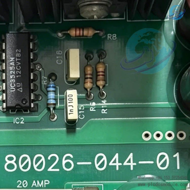
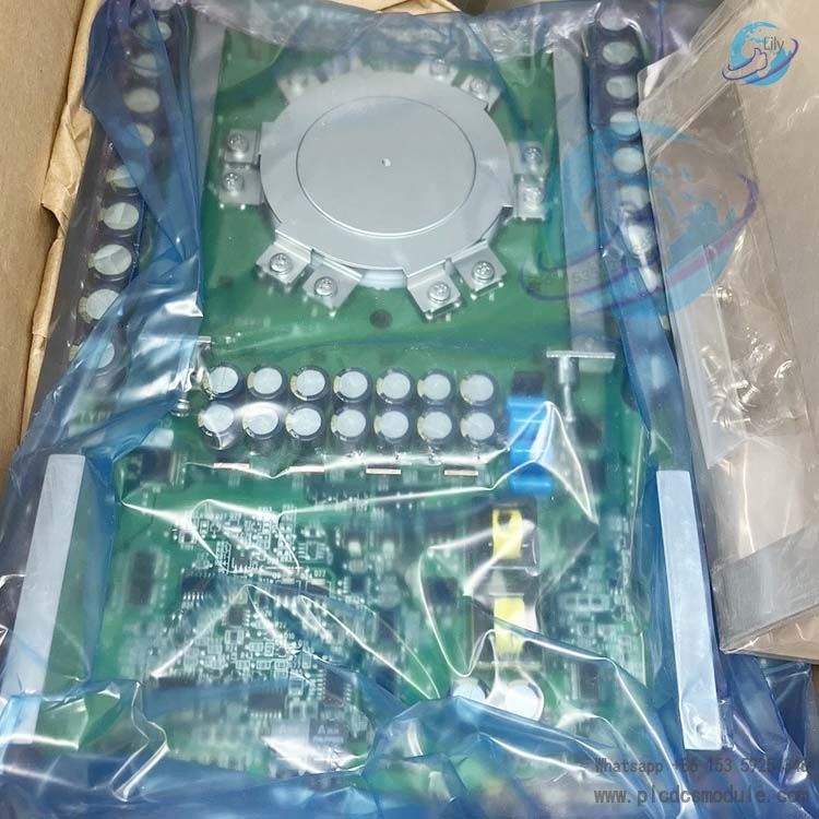
A‑B 80026‑044‑01 belongs to the original Allen‑Bradley (Rockwell Automation) 80026 product lineup and was originally OEM-manufactured by Emerson. It serves as an integrated isolating switching
power supply board exclusively built into PowerFlex medium & high-voltage variable frequency drives and Bulletin 1503 high-voltage soft starters.
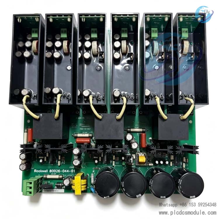
This unit supplies multiple isolated regulated DC power to the unit’s main control DSP, IGCT/SGCT drive circuits, signal acquisition modules and cooling fan control loops, functioning as the core power component for the power drive and control system of high-voltage converter assemblies.
This variant is the original standard version within the entire 80026‑044 family; revised derivative models carry suffix designations such as -02, -03, -06-R, compatible with high-voltage drives rated at 3kV, 6kV and 10kV.
Technical Specifications
Electrical Input ParametersSupports wide-range AC input of 100~240V, 50/60Hz for unit auxiliary power, compatible with dual power supply modes: cabinet 220V mains power and low-voltage output from isolation transformer.
Multiple Regulated Outputs① +5V/3A for main control CPU and communication boards;② ±24V/1.8A for IGCT gate drive circuits;③ +15V/1A for voltage & current sampling and temperature monitoring circuits.Output ripple of all channels <0.8% FS, voltage regulation accuracy ±1%.
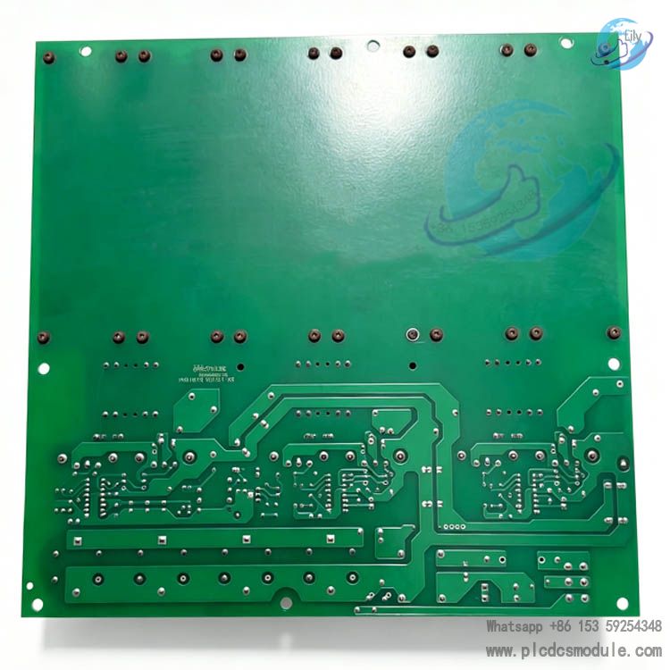
Physical DimensionsPCB dimension: 254mm×406mm, net weight: 210g; vertically embedded slot mounting, IP30 protection class (for fully enclosed cabinet installation).
EMC PerformanceEquipped with X/Y safety capacitors and common-mode choke inductors on-board, compliant with industrial immunity standard IEC61000-6-2. Ensures stable operation under high-harmonic grid conditions with frequent IGCT switching of variable frequency drives.
Redundant Component DesignKey filter capacitors and switching transistors adopt dual-channel parallel redundancy. Aging of a single component will not trigger full-board power loss, improving mean time between failures (MTBF ≥ 85,000 hours).
Core Advantages
Multi-channel Electrical Isolation ArchitectureHigh-frequency multi-winding transformers onboard realize power isolation. The three output circuits (+5V for main control, ±24V for drive, +15V for detection) are mutually galvanically isolated. Withstanding insulation voltage of 3000 VAC between high-voltage section and low-voltage control section prevents control-circuit breakdown induced by high-voltage creepage, suitable for harsh EMI environments of high-voltage inverters.
Multi-stage Full-Condition ProtectionFive levels of hardware protection are integrated: input undervoltage, input overvoltage, output overcurrent, output short-circuit and onboard overtemperature. The unit locks output instantly and triggers fault LED upon abnormality to avoid cascaded damage of IGCT power modules and drastically reduce overall unit burnout risks.
Wide Temperature Range for Severe Working ConditionsConstructed with industrial-grade original components. Standard operating temperature spans from -10℃ to +60℃; cold start down to -25℃ for short duration. Passes vibration aging test at 5~57Hz with 0.38mm amplitude, applicable to high-vibration sites such as metallurgy and mining plants.
Standard Original Pin DefinitionGold fingers and terminal connectors comply with original factory slot specifications for plug-and-play replacement without wiring modification. All variants with 044 suffix share identical hardware pin compatibility; on-site replacement finishes within 5~10 minutes to minimize equipment downtime for maintenance.
High Efficiency & Low Power ConsumptionAdopts original soft-switching PWM topology. Full-load power conversion efficiency ≥87%, no-load power consumption<3.5W. Low standby heat generation lessens cabinet heat dissipation burden and slows ageing of adjacent capacitors.
Visual Self-Diagnosis FunctionThree onboard status LEDs (Input Ready, Output Normal, Fault Alarm) enable rapid fault pinpointing without external measuring instruments and lower maintenance difficulty.
FAQ
Q: Can 80026-044-01 and 044-06-R be directly interchanged?A: They feature fully compatible pin assignment and mounting dimensions. Model 06-R is an upgraded revision with backward compatibility to replace 01 version. However, the 01 variant is not recommended as a substitute for factory-new units originally equipped with 06-R, as insufficient output power may occur occasionally.
Q: Are there domestically-made alternative replacement boards? How is their compatibility?A: Third-party imitation substitute boards are available on the market at lower cost, yet they fail to meet requirements on isolation withstand voltage and EMC performance. Breakdown of the complete high-voltage drive is likely under operational high-voltage conditions; original OEM boards are preferred for factory equipment maintenance.
Q: Steady red fault LED after power-up, what are typical fault causes?A: ① Missing phase of incoming AC220V supply or input voltage below 180V triggering undervoltage protection; ② Short-circuit caused by breakdown of onboard output capacitors; ③ Shorted IGCT in rear drive circuit dragging down power supply output. Isolate loads step by step for fault confirmation.
Q: Voltage reading normal under no-load condition but drops sharply with load followed by alarm?A: Increased internal resistance from aged internal power switching components or degraded capacitance of output filter capacitors results in poor load capacity. Complete board replacement is advised instead of discrete repair of SMD components.
Q: Frequent overtemperature protection shutdown in hot summer, improvement solutions?A: Remove dust accumulated inside converter cooling ducts, install additional cabinet axial fans to keep ambient temperature around the board below 55℃. Replace the entire power board if capacitor degradation is confirmed.
Q: No LED illumination and total power failure on the board, troubleshooting sequence?A: Step1: Verify external AC220V incoming power; Step2: Check blown input fuse on the board; Step3: Inspect damaged onboard rectifier bridge. If all above items are intact, the internal main PWM IC is damaged and spare board replacement is required.


 3005319639