


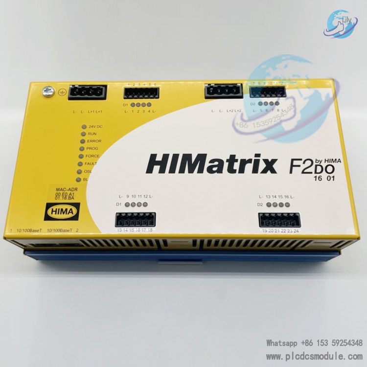
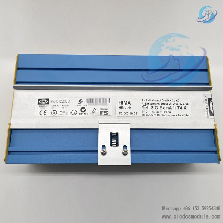
HIMA HIMatrix F2 DO 16 01 (Part No. 982200480) is a safety remote digital output module manufactured by HIMA, Germany. It is specially developed for the HIMatrix safety controller system and compatible with SILworX programming software. Equipped with 16 non-electrically isolated digital output channels, it communicates with the main controller via SafeEthernet to expand system I/O points.
Certified by TÜV, the module complies with the highest safety levels including SIL 3 (IEC 61508), Cat.4 (EN 954-1) and PL e (EN ISO 13849-1). It also holds ATEX Zone 2 explosion-proof approval. As a core remote I/O device for industrial safety automation, it is widely deployed in industrial sites requiring functional safety and explosion protection.
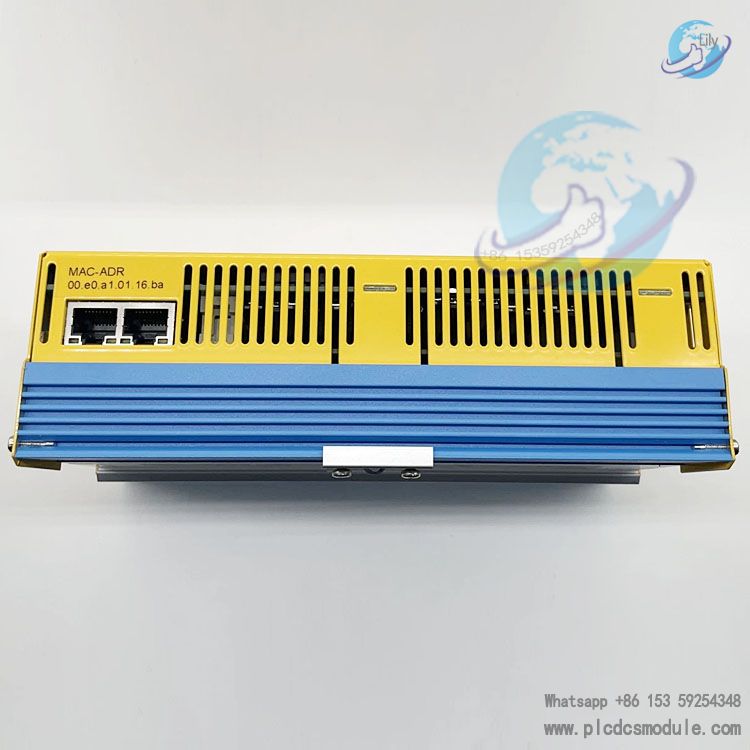
This model is designed for HIMatrix systems running OS Version 7 or above and is incompatible with ELOP II Factory programming tool. Its factory default IP address is 192.168.0.99, and the default SRS address is 60000.200.0.
Download

Product Features
1. Basic Hardware Specifications
Output SpecificationsTotal 16 digital output channels divided into two groups: Group D1 (Channels 1-4, 9-12) and Group D2 (Channels 5-8, 13-16). Maximum load per channel is 2 A at 40°C and 1 A at 60°C. The maximum total current for each group is 8 A, and 16 A for the entire module. Minimum load per channel is 2 mA. It supports inductive loads up to 500 mH with no freewheeling diode required. For extended service life, the manufacturer recommends installing protective diodes on the load side.Power Supply SpecificationsRated 24 VDC power supply with a permissible voltage fluctuation range of -15% to +20%. Quiescent current per unit is approximately 0.2 A. A 10 A time-delay fuse shall be installed externally for protection.
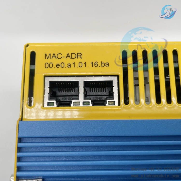
Physical StructureMetal enclosure with IP20 protection degree. Equipped with 2 RJ45 Ethernet ports, reset hole, status indicator array and 24 wiring terminals. Response time ≥ 20 ms. No backup battery is fitted.
Environmental SpecificationsPollution Degree II in compliance with IEC/EN 61131-2. Approved for installation in ATEX Zone 2 hazardous areas only. The mounting enclosure shall meet IP54 or higher protection rating.
2. Safety & Fault Logic
- Communication interruption: All outputs hold the preset safe state to prevent unintended equipment operation.
- Single channel overload / short circuit: The faulty channel cuts off automatically and retries periodically, while other channels operate normally. The FAULT LED flashes and a channel fault code is reported.
- Module overall failure: All 16 outputs de-energize immediately and switch to safe state. The ERROR and FAULT LEDs stay on, and the system locks the fault status.
- ESD protection: The module is electrostatic-sensitive. Always wear an anti-static wrist strap during handling and installation, and ensure the working area is properly protected against static electricity.
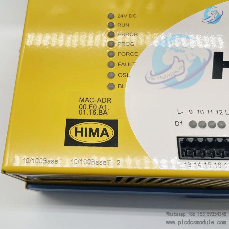
3. LED Indicator Definitions
LED indicators serve as key references for on-site quick diagnostics, categorized into four types:
- Power LED (24 VDC, Green): Steady on = Normal power supply; Off = No power input.
- System LEDs: RUN (Green), ERROR (Red), PROG (Yellow) and FAULT (Yellow), indicating operating status, system fault, program download and module abnormality respectively.
- Ethernet Communication LEDs: Green LED for duplex / collision status; Yellow LED for link and data transmission status.
- I/O LEDs (Yellow): DO1 ~ DO16 corresponding channel indicators. Steady on = Channel output active; Off = Channel de-energized.
4. Network & Address Parameters
Default AddressesIP address: 192.168.0.99; SRS address: 60000.200.0 (for SILworX exclusive use).
Common UDP Ports8000 (programming tool communication), 6010 (SafeEthernet communication), 123 (time synchronization), 8004 (SILworX configuration).
Reset FunctionPress and hold the reset button with an insulated tool and restart the device to restore IP and SRS addresses to factory defaults. All custom user accounts will be cleared, while the default administrator account (blank password) remains active.
Core Advantages
High Safety Level & Multi-Fault Protection
Adopting end-to-end safety design, the outputs will automatically switch to de-energized safe state in case of single-channel failure, module hardware fault or communication interruption. It features short-circuit detection, overload protection and temperature monitoring. The FAULT LED lights up and relevant fault codes are generated upon faults. Complying with mainstream global industrial safety standards, it fully meets functional safety requirements for high-risk operating conditions.
Stable & Reliable Communication
Equipped with dual RJ45 Ethernet ports supporting 10/100Base-T, auto-negotiation and auto-crossover. Secure data transmission is realized via SafeEthernet. Dedicated UDP ports are assigned for programming, time synchronization and safety data transfer. With strong anti-interference capability, it adapts to complex industrial network environments.
Wide Operating Range & Explosion-Proof Performance
Operating temperature: 0°C ~ +60°C; Storage temperature: -40°C ~ +85°C. It features IP20 protection degree and is applicable at altitudes up to 2000 meters. Certified for ATEX Zone 2, the module can be directly installed in Category 2 hazardous areas without additional enclosure modification.
High Integration & Convenient Wiring
16 digital output channels are integrated into a compact metal housing. Dimensions: 207mm×114mm×66mm, weight: 0.85kg. It supports standard 35mm DIN rail mounting. Terminals are clearly zoned with dedicated grounding terminals for each channel group, which standardizes wiring and reduces circuit faults.
Easy Diagnosis & Maintenance
Full-status LED indicators for power, system, communication and I/O enable intuitive status checking. Fault codes and diagnostic logs can be read online via programming software. A reset button is available to restore network parameters to factory defaults with one click, greatly simplifying on-site commissioning and troubleshooting.
Application Scenarios
Designed to meet dual core requirements of industrial functional safety and explosion protection, this module is compatible with HIMatrix and HIMax safety control systems. Its main application scenarios are listed below:
Petrochemical IndustryDeployed in ATEX Zone 2 hazardous areas such as refining units, chemical reactors and oil & gas transmission pipelines. It delivers control outputs for emergency shutdown valves, audible & visual alarms and safety interlock actuators.
Power & Energy IndustryApplied to boiler safety interlocks and turbine protection systems in thermal power and gas-fired power plants, providing safe output control for trip circuits and auxiliary equipment.
Machinery Manufacturing IndustryUsed for large machine tools, automated production lines and lifting equipment. Compliant with EN ISO 13849 PL e safety requirements, it controls safety gates, emergency stop circuits and braking mechanisms.
Rail Transit & PortsAdopted for port handling equipment and ground safety interlock systems of rail transit. It expands remote I/O points to realize distributed safety control.
Pharmaceuticals & Fine ChemicalsIntegrated into Safety Instrumented Systems (SIS) in explosion-proof workshops and aseptic production lines to protect personnel and equipment during production.
Usage Restrictions
This module functions only as a remote I/O expansion unit and cannot run user programs independently. It must work with HIMA main safety controllers. Multi-master mode is not supported, and it only executes commands issued by the main controller.
Selection Recommendations
For new projects with controller system version 7 or above, prioritize model 982200480 (this unit).
For existing legacy devices running OS version below 7 and using ELOP II Factory software, select model 982200406.
If on-site output channels are fewer than 8 and budget is limited, choose F3 DO 8 01.
To adopt a unified software platform and facilitate future system upgrades, the fully compatible F3 series is the preferred option.
Frequently Asked Questions
Q: How to distinguish between F2 DO 16 01 (982200480) and 982200406? Are they interchangeable?A: The two models share identical hardware, differing only in firmware and compatible software. Model 982200480 works with SILworX (system OS ≥ 7), while 982200406 is for ELOP II Factory (system OS < 7). They cannot be directly swapped. Cross-version application requires firmware re-flashing and full program reconfiguration.
Q: Does this module have SIL 3 certification? Can it be used in Safety Instrumented Systems (SIS)?A: Certified by TÜV, it meets the highest safety levels of SIL 3, PL e and Cat.4, fully complying with SIS application standards. It is applicable to SIS in high-risk industries such as petroleum and chemical engineering.
Q: What power supplies are supported? Can a standard industrial 24V power supply be used directly?A: Only SELV/PELV isolated 24VDC power supplies are permitted, with a permissible voltage fluctuation range of -15% to +20%. Standard non-isolated 24V industrial power supplies are prohibited. A 10A time-delay fuse must be installed externally.
Q: Are additional accessories required for purchase? What is included in the standard package?A: The standard package contains the module body and address label (marked with IP/SRS information). Separately purchase 35mm DIN rail, shielded Ethernet cables, terminal blocks and anti-static wrist strap. An IP54-rated enclosure is additionally required for explosion-proof locations.
Q: Cannot connect via SILworX due to forgotten IP address. How to restore factory settings?A: Use an insulated fine tool to press and hold the reset button inside the reset hole, then power cycle the module. Keep holding the button for no less than 20 seconds after restart. The IP address will revert to 192.168.0.99, the SRS address will be restored to default, and the administrator password will be cleared.
Q: A single DO channel frequently reports overload faults with no short circuit detected on the load. What are the causes?A: 1. Adjacent channels operating at full 2A load simultaneously cause accumulated heat and trigger overtemperature protection. Long-term full load on adjacent channels is not recommended by the manufacturer.2. The inductance of the load exceeds 500mH.3. Loose terminal wiring leads to excessive contact resistance. Inspect wiring and load parameters one by one.
Q: The red ERROR LED stays on and all outputs fail. What are the emergency solutions?A: First read the fault code via SILworX. Perform a remote restart if it is a temporary system error. If the fault persists after restart, the module is diagnosed with hardware damage. Shut down the system and replace it with an identical model, then download the original configuration to resume operation.
Q: What mandatory maintenance requirements apply when the module is installed in ATEX Zone 2 hazardous areas?A: 1. All disassembly, assembly and wiring operations must be carried out with power disconnected (except when the hazardous gas atmosphere is confirmed eliminated).2. The mounting enclosure shall have a protection rating of no less than IP54.3. Full functional safety tests shall be performed every 10 years.4. Do not modify internal hardware or remove explosion-proof markings of the module.


 3005319639