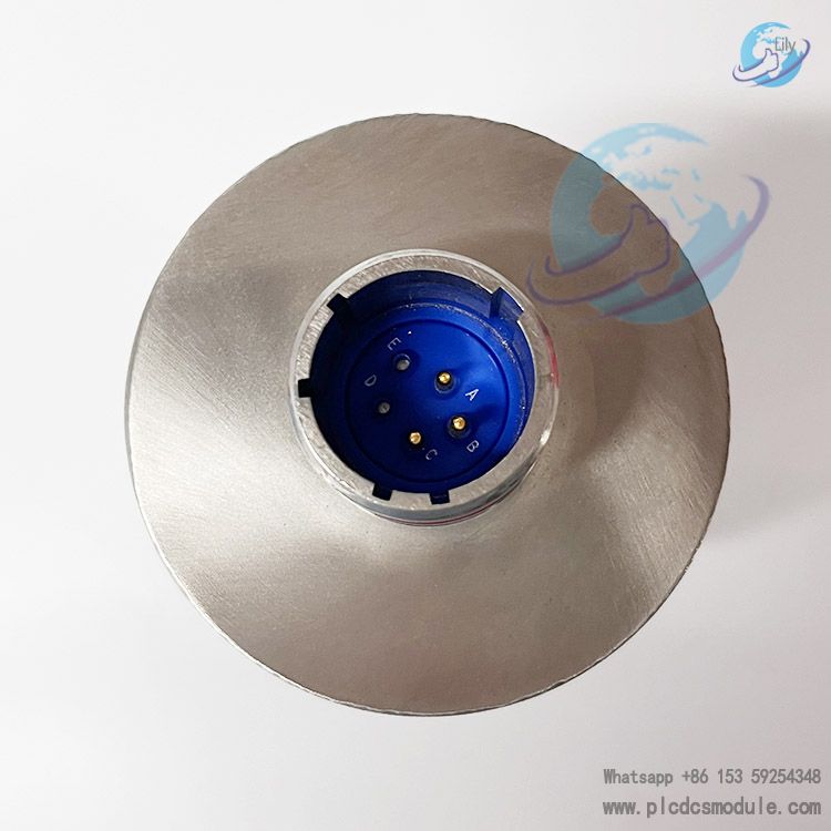
The model 362A1052P404 is a custom ordering variant matched to complete gas turbine units. It fits the mounting bases and control systems of GE heavy-duty and light-duty gas turbines. Certified to global standards for explosion protection, electromagnetic compatibility (EMC) and functional safety, this detector delivers stable long-term performance in harsh gas turbine enclosure environments featuring high temperatures, dust, intense electromagnetic interference and severe vibration. It serves as the standard factory flame detection sensor for thermal power plants and combined-cycle power stations.
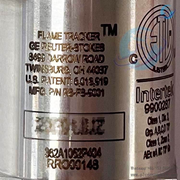
Manufacturer & Production Entity
Model Differentiation Rules
Core Sensing Technical Principle
Core advantages of SiC material: High temperature resistance, resistance to radiation aging, no risk of failure due to vacuum leakage, and far longer service life than conventional ultraviolet phototubes. It offers superior penetration through flue gas and water mist, enabling stable capture of weak flame signals even under gas turbine low-load and steam purging operating conditions.
Signal conversion logic: The light-sensing chip converts ultraviolet light intensity into a tiny current, which is linearly converted into a standard two-wire 4–20 mA analog output via an internal amplifier circuit. No additional relay contacts are required, simplifying on-site wiring and cabinet acquisition channel configuration.
Electrical Specifications
Power Supply & Output
Supply voltage: DC 18V~30V, nominal operating voltage 24 VDC
Output format: Two-wire loop-powered 4–20 mA analog signal; power supply and signal share the same two cables
Signal definition: 4 mA = No flame / sensor fault; 20 mA = Full-scale flame intensity. Intermediate current values correspond linearly to flame ultraviolet radiation intensity, and the control system allows custom configurable flame loss threshold
Power consumption: Max. 22 mA (under full flame 20 mA output condition)
Response Performance
Flame signal response time: <25 ms. It instantly detects sudden flameout and meets the millisecond-level fuel cut-off interlock safety requirements of gas turbines
Built-in Continuous Built-In Test (BIT): The sensor real-time monitors faults of the chip, amplifier circuit and power supply loop. A fault condition locks the output at 4 mA, enabling the control system to directly identify sensor failure and distinguish "actual flame loss" from "probe damage"
Matching Cable Specifications
Mechanical Structure & Environmental Parameters
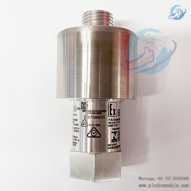
1. Mechanical Structure
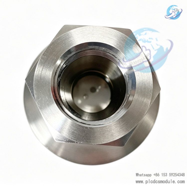
- Housing material: One-piece forged 316 stainless steel enclosure, resistant to gas condensate and sulfur corrosion
- Mounting interface: Standard external hexagonal threaded mounting base. The thread specification of model 362A1052P404 matches the original sighting tube sleeves of GE gas turbines, supporting installation with air-cooled sleeves
- Ingress protection rating: IP65, dust-tight and protected against water jets, suitable for high-humidity and dusty environments inside gas turbine enclosures
- Overall dimensions: Total length approx. 115 mm, housing diameter 72 mm. Lightweight design reduces fatigue damage to the probe caused by unit vibration
2. Environmental Tolerance Indexes
- Operating temperature of probe body: -40℃~+85℃. When cooling air is passed through the sighting sleeve, it can withstand radiant high temperatures over 300℃ from the furnace wall
- Vibration resistance standard: Complies with IEC 60068-2-6 gas turbine vibration test specification, capable of enduring continuous low-frequency and high-frequency vibration during gas turbine startup/shutdown and full-load operation
- Storage temperature: -50℃~+120℃
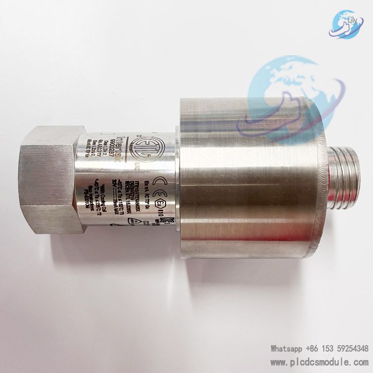
Explosion-proof certifications: North America Class I Div 2 Groups C/D; EU ATEX II 3G Ex nA IIB T4 Gc for Zone 2; EMC complies with EN 61000 industrial electromagnetic compatibility standards
Product Advantages
Long service life and low maintenance requirements
The solid-state SiC sensor chip contains no vacuum components, eliminating common failures of traditional UV tubes such as vacuum leakage and cathode aging. Its average field MTBF (Mean Time Between Failures) reaches no less than 8 years, greatly cutting unit shutdowns for sensor replacement.
Simplified two-wire wiring design
Only two shielded cables handle both power supply and signal transmission, cutting wiring costs by half compared with four-wire flame detectors, making it ideal for retrofit projects of aging gas turbines.
Superior anti-interference performance
Dual suppression via narrowband UV spectral filtering and hardware filter circuits eliminates false alarms triggered by sunlight, electric arcs, furnace thermal radiation, and electromagnetic interference from frequency converters.
Linear quantification of flame intensity
The continuous 4–20 mA analog output intuitively reflects flame strength. The control system can monitor flame stability during gas turbine ignition, low-load and full-load operating conditions to support combustion optimization, instead of merely providing an on/off flame presence signal.
Built-in automatic fault diagnosis
No extra test instruments are required. The control system can identify four distinct states including probe open circuit, short circuit, chip failure and flame loss simply by reading the current value, streamlining troubleshooting work.
Full OEM compatibility for complete turbine sets
Model 362A1052P404 is factory-calibrated for GE gas turbine control systems. It offers plug-and-play compatibility with Mark VIe, Mark VI and Speedtronic series turbine controllers without on-site recalibration.
Application Scenarios
Primary Applications
Combustion flame monitoring for all GE heavy-duty and light-duty gas turbines deployed in combined-cycle power plants and distributed energy stations. The part number 362A1052P404 is a standard OEM component for complete turbine units.
Extended Industrial Applications
BMS combustion safety systems for industrial boilers, heating furnaces and cracking furnaces burning natural gas, heavy oil and pulverized coal.
Applicable Fuels
Hydrocarbon fuels including natural gas, blast furnace gas, liquefied petroleum gas, diesel and kerosene. Not suitable for pure hydrogen combustion applications, as hydrogen generates no ultraviolet radiation.
Differentiation of Models in the Same Series
| Model | Explosion-Proof Rating | Core Differences | Application Scenarios |
|---|---|---|---|
| RS-FS-9001 (362A1052P404) | Class I Div 2 / ATEX Zone 2 | Standard two-wire 4–20 mA SiC UV flame probe | Conventional gas turbines and industrial boilers (this model) |
| RS-FS-9004 | Class I Div 1 / ATEX Zone 1 | Intrinsically safe design with isolated circuits | Coal chemical plants and high-risk explosion-prone furnaces |
| RS-FS-9009-03 | Class I Div 2 | Withstands 325 ℃ high temperature without cooling air | Small high-temperature heating furnaces without air cooling supply |
Frequently Asked Questions
Q1: What are the differences between part numbers 362A1052P404 and 362A1052P004?
A1: The P404 complete kit comes with standard aviation connectors and matched threaded mounting assemblies, ready for direct installation on units upon delivery. The P004 only includes the bare probe body without connectors or auxiliary fittings. Separate cables and connectors must be purchased individually, and this variant is intended for standalone sensor core replacement on existing equipment.
Q2: Can this detector directly replace flame sensors of the same specification from other brands?
A2: Though the mounting thread dimensions are interchangeable, its 4–20 mA output curve and relay logic are tailored for GE gas turbine control systems. Direct substitution with Honeywell or Siemens probes will cause signal mismatch and false interlock trips. Cross-brand replacement requires simultaneous modification of threshold parameters within the control program.
Q3: Can RS-FS-9001 be directly adopted for projects located in Zone 1 hazardous chemical areas?
A3: The RS-FS-9001 carries a Zone 2 explosion-proof rating. RS-FS-9004 with intrinsically safe piping accessories must be selected for Zone 1 high-risk hazardous areas; the 9001 model fails to meet acceptance standards for Zone 1 locations.
A4:
Step 1: Verify water cooling system for water loss, which may burn out the quartz window under high temperature.
Step 2: Dismount the probe and clean carbon deposits and grease on the window.
Step 3: Measure the 24 VDC supply voltage to check for excessive voltage drop.
Step 4: Inspect aviation connectors for loose wiring terminals.
Final step: Use a signal simulator to verify whether the sensor core is damaged.
Q5: The unit suffers frequent false flameout alarms where the signal randomly drops to 4 mA during normal combustion. How to resolve this issue?
A5: Check proper grounding of the shielded cables; high-power frequency converters in the workshop generate electromagnetic interference that distorts signals. Adjust the probe angle to expand the flame viewing field, lower the flame detection threshold in the control system, and remove soot blockages on the lens surface.
Q6: What water quality requirements apply to the circulating water for the water cooling sleeve?
A6: Only softened deionized cooling water is permitted; hard water containing sediment and impurities is prohibited. The inlet water temperature shall be maintained between 20°C and 40°C with continuous water circulation. Cooling water must keep flowing for an additional 30 minutes after unit shutdown before cutting off the water supply.
A7: For conventional thermal power gas turbines, lens cleaning shall be conducted quarterly, and full calibration with a flame simulator shall be performed annually. For high-dust or heavy oil combustion operating conditions, the calibration cycle shall be shortened to six months, with linear 4–20 mA output test data recorded and filed for archiving.
Recommended Models of the Same Brand
RS-FS-9001 (362A1052P404): Ultraviolet Flame Detector
RS-FS-9004 (362A1052P104): Intrinsically Safe Ultraviolet Flame Detector
RS-FS-9006-MFR (362A1379P001): Flame Detector for Aero-Derivative Gas Turbines
RS-FS-9009-03 (FTD325): Dry Uncooled Flame Sensor
RS-FS-9010-03 (FTD325): Division 1 Explosion-Proof Dry Flame Sensor
RS-FS-9009-03-25X: Low-Gain Dry Detector for Weak Flame Detection
RS-FS-9010-03-25X: Division 1 Explosion-Proof Low-Gain Dry Detector
RS-FS-9101: Wide-Field Long-Range Ultraviolet Flame Detector
RS-FS-9100: General-Purpose Flame Monitoring Probe for Industrial Boilers
LG1093AA: Legacy Geiger-Müller Tube Flame Sensor (Compatible Replacement Model)