


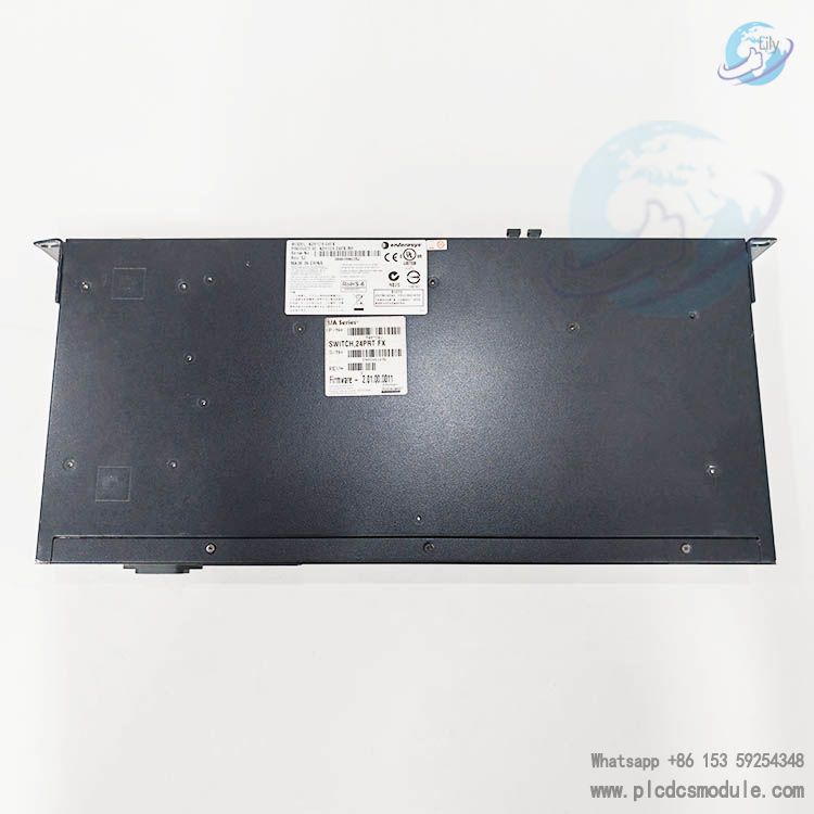
ENTERASYS/FOXBORO A2H124-24FX-RH ethernet switch.The A2H124-24FX-RH is a stackable fast Ethernet switch that can meet diverse network requirements. It is equipped with 24 100BASE-FX multimode MT-RJ ports, 2 SFP slots (supporting various Mini - GBIC interface modules), and 2 1000BASE-T RJ45 ports, which can be used for stacking or as standard Ethernet ports. This switch supports redundant DC power supply and has a stacking function. Up to 8 switches can be stacked and managed uniformly by a single management platform.
Data sheet:
![]() A-Series Fast Ethernet Stackable L2 Switch.pdf
A-Series Fast Ethernet Stackable L2 Switch.pdf
![]() Enterasys A2H124-24FX Hardware Installation Manual.pdf
Enterasys A2H124-24FX Hardware Installation Manual.pdf
Performance Specifications
Throughput and Switching Capacity: The throughput line rate is 9.5 Mpps (for a single switch)/76.2 Mpps (for a stack), and the switching capacity is 12.8 Gbps (for a single switch)/102.4 Gbps (for a stack). In terms of stacking capacity, there are no dedicated stacking ports, and the 10/100/1000 ports can be used for stacking or uplink connections. The aggregate throughput is the same as the switching capacity.
MAC Address Table and VLAN Support: It supports 8,000 MAC addresses. For VLANs, there are 4,096 VLAN IDs, and each stack has 1,024 VLAN entries.
Physical Characteristics
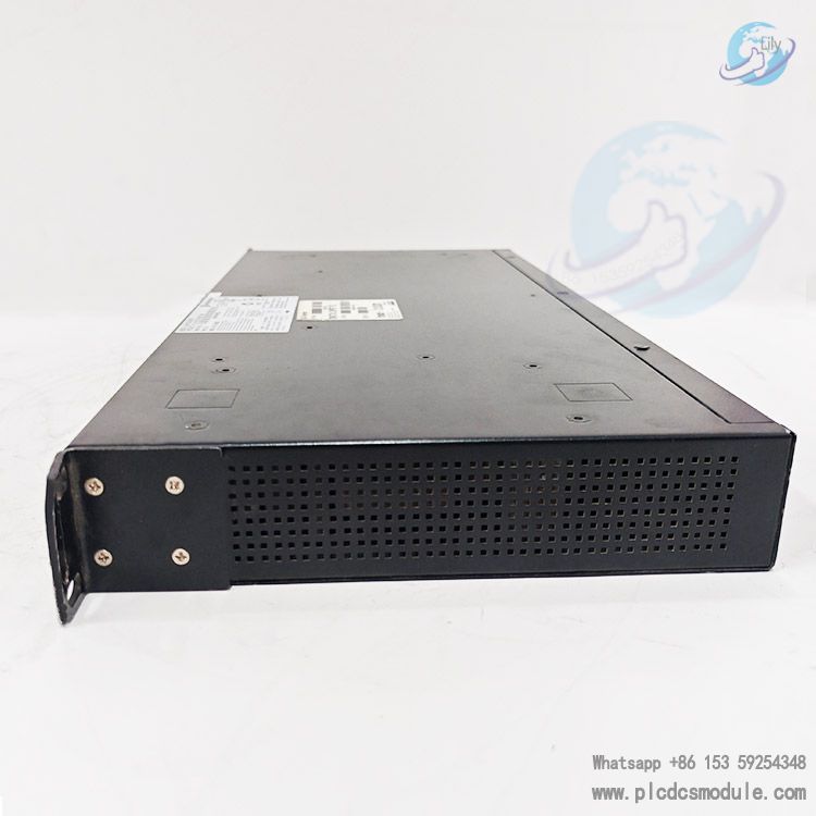
Dimensions and Weight: The dimensions are H: 4.4 cm (1.73”), W: 44.1 cm (17.36”), D: 21.0 cm (8.27”), and the net weight is 2.7 kg (5.94 lb).
Physical Ports: It has 24 100Base - FX MTRJ fiber - optic ports, 2 mini - GBIC ports, 2 10/100/1000 stacking/uplink RJ45 ports, 1 DB9 console port, and 1 RPS port.
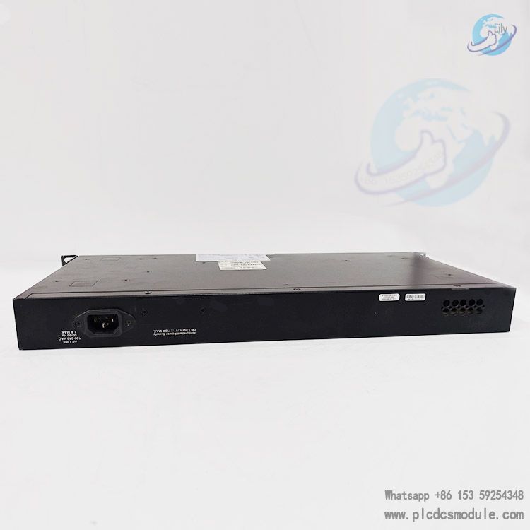
Power Requirements: The rated input voltage is 100 - 240 VAC, the input frequency is 50 - 60 Hz, the input current is 1.0A Max, and the power consumption is 59 watts. The standard operating temperature ranges from 0°C to 50°C (32°F to 122°F), the non - operating temperature ranges from - 40°C to 70°C (- 40°F to 158°F), the heat dissipation is 201 BTUs/Hr, the operating humidity is 5% - 95% non - condensing, the vibration complies with the IEC 68 - 2 - 6 and IEC68 - 2 - 36 standards, and the shock complies with the IEC 68 - 2 - 29 and IEC 68 - 2 - 32 standards.
PoE Specifications
It does not support the 802.3af standard, and there is no description related to system PoE.
Hardware Installation
Pre-installation Preparation: Notify the network administrator, follow the procedures, and do not connect to the network until the correct IP address is set. Prepare tools such as a Phillips screwdriver.
Unpacking and Inspection: Check the items in the packaging box and inspect the appearance of the switch for any damage.
Installing Mini-GBIC Modules: Take anti-static measures before installation. Insert the module into the slot according to its type and lock it in place. When removing the module, release the locking tab first and then pull it out.
Selecting the Installation Location: It can be installed on a flat surface or in a 19 - inch rack. For flat-surface installation, install rubber feet and pay attention to the installation location, temperature, ventilation, and power source distance. For rack installation, use the matching mounting brackets and screws, and pay attention to the stability of the rack, the location of the power outlet, and ventilation.
Stacking Connection: The stacking methods include closed - loop and daisy - chain. Use standard UTP cables and connect up to 8 switches. Configure the switches after connection. When installing a new stack, power on the switches one by one. When adding a new switch to an existing stack, connect the cables according to the stacking topology and then power on the new switch.
Power Connection: It supports 100-240VAC power. When connecting to the AC power supply, pay attention to observing the status of the CPU LED. It can be connected to the C2RPS-SYS redundant power system, but note that it cannot be connected to the PoE redundant power supply.
Console Connection: Connect an RS232 DTE interface cable to the console port for local management. Select the appropriate cable according to the connected device and set the terminal parameters.
Network Connection: Connect fiber-optic or UTP cables to the corresponding ports. Ensure that the devices are powered on and check the connection status. If the connection is not established, troubleshoot the problems.
Completing the Installation: After the connection is completed, log in to the switch management interface through a local device for configuration. You can use CLI commands or WebView for management. After a successful installation, organize and secure the cables.
Customers who purchased this product are also browsing the following products:
FOXBORO FCP270 P0917YZ Field Control Processor
FOXBORO/Extreme X440-G2-24fx-GE4 RH102ANindustrial Ethernet switch
TRICONEX 3009X Main Processor for System modules Tricon CX MP3009X
Rockwell ICS TRIPLEX T8110B Trusted TMR Processor Module


 3005319639