


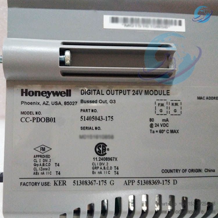
The Honeywell CC-PDOB01 51405043-175 is a 24Volt digital output module specifically designed for industrial automation scenarios. Its core positioning is to serve as the "command execution hub" between the control system and on-site executive equipment. It converts digital control signals issued by the controller into electrical signals capable of driving external equipment, thereby achieving accurate and reliable control of loads in industrial on-site environments.
This module is highly compatible with the architecture of Honeywell Experion PKS control system. It adopts a modular hardware design and customized signal driving technology. Different from general-purpose digital output modules, it has undergone targeted optimizations in terms of load compatibility, signal response speed, and fault self-healing capability. It can directly drive common industrial executive components such as relays, contactors, and solenoid valves, and is widely used in industrial scenarios with strict requirements for the real-time performance and stability of control commands. As such, it is a key component that ensures production processes operate efficiently in accordance with preset logic.
Performance Parameters
Output Channels and Load Capacity
Number of Output Channels: 16 independent digital output channels. Each channel can be configured with load parameters individually, supporting parallel control of multiple devices.
Output Voltage: Standard 24VDC (allowing a fluctuation range of ±10%, i.e., 21.6-26.4VDC), compatible with mainstream low-voltage executive equipment in the industrial field.
Maximum Single-Channel Output Current: 2A (for continuous operation) and 3A (instantaneous peak current), enabling direct driving of medium-to-high load devices such as small motors and high-power solenoid valves.
Load Type Compatibility: Supports resistive, inductive, and capacitive loads. No additional buffers are required (when inductive loads ≤100mH), making it suitable for different types of on-site equipment.
Signal Characteristics
Output Response Time: ≤1ms (from receiving the controller command to completing the output state switch), ensuring delay-free execution of control commands and meeting the needs of high-speed production cycles.
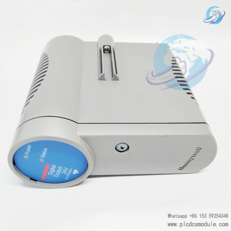
Output Status Indication: Each channel is equipped with an independent LED indicator (green = on, off = disconnected). The red light remains on in case of a fault, enabling visual judgment of the channel’s working status.
Signal Isolation: Adopts photoelectric isolation technology (isolation voltage of 2500VAC for 1 minute), realizing electrical isolation between the module’s internal circuit and external loads to prevent interference from load-side voltage fluctuations on the control system.
Power Supply and Power Consumption
Operating Power Supply: Requires an external 24VDC DC power supply (separate power supply, isolated from the control system power supply) with a power supply ripple ≤100mVpp.
Module Power Consumption: Static power consumption ≤3W (when no load is connected); total power consumption ≤35W under full-load operation (all 16 channels with 2A loads each). The low-power design reduces the heat dissipation pressure of the system.
Environment and Protection
Operating Temperature Range: -25°C to +65°C. Compared with conventional modules, it has an expanded low-temperature tolerance range, suitable for scenarios such as outdoor control cabinets in cold regions.
Storage Temperature Range: -40°C to +85°C, facilitating long-term inventory storage.
Relative Humidity: 5% to 95% (non-condensing). It has passed humidity cycle tests, making it adaptable to humid workshop environments such as food processing and pharmaceutical facilities.
Protection Rating: The module itself has an IP20 rating (after panel mounting), and the terminal interfaces feature a dust-proof design to prevent poor contact caused by dust accumulation.
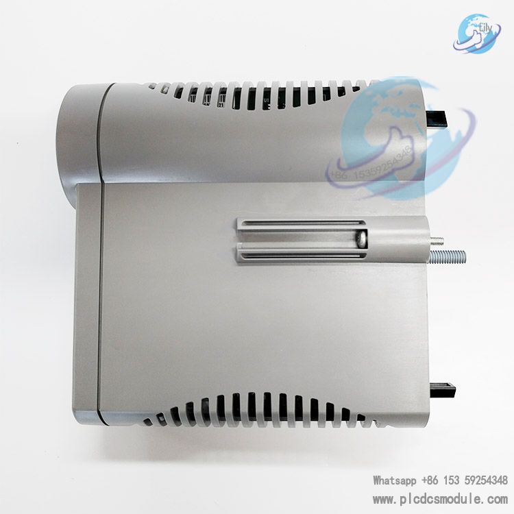
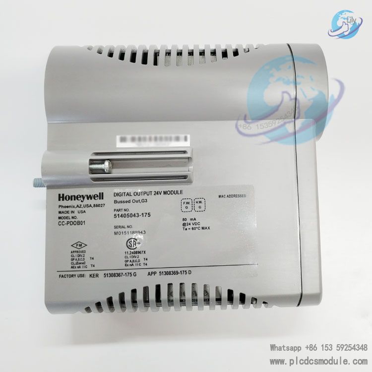
Physical and Mounting Specifications
Overall Dimensions: 106mm (width) × 150mm (height) × 75mm (depth). It adopts a compact design, compatible with standard 19-inch industrial cabinets.
Mounting Method: Only supports 35mm DIN rail mounting (equipped with quick-release buckles, enabling fixation without tools).
Weight: Approximately 420g, including a metal reinforced housing that enhances impact resistance (impact resistance rating IEC 60068-2-27: 15g acceleration, 11ms pulse).
Advantages and Features
Wide Load Compatibility, Reducing Peripheral Accessories
Different from most digital output modules that only support resistive loads, this module is equipped with a built-in load adaptation circuit, enabling direct driving of resistive, inductive, and capacitive loads (inductive loads ≤ 100mH, capacitive loads ≤ 100μF). There is no need to install additional freewheeling diodes (for inductive loads) or current-limiting resistors (for capacitive loads), which reduces system integration costs and the complexity of cabinet wiring.
Fault Self-Diagnosis and Localization, Shortening Maintenance Time
The module is equipped with a real-time fault monitoring function, which can detect faults such as overcurrent (single-channel current > 2.5A), short circuit, and power supply undervoltage (< 21.6VDC). Faulty channels are synchronously reported through LED indicators (independent fault light for each channel) and control system alarm signals. Maintenance personnel do not need to check each channel one by one—they can quickly locate the fault point, shortening maintenance time by more than 60%.
High Anti-Interference and Electrical Isolation, Ensuring System Stability
It adopts a dual anti-interference design of "photoelectric isolation + metal housing shielding":
The 2500VAC photoelectric isolation can block electrical interference between the load side and the control system.
The metal housing can shield external electromagnetic radiation (such as interference generated by workshop motors and frequency converters).
This ensures that in electromagnetic complex environments (e.g., metallurgical workshops, automobile welding workshops), the output signal does not act incorrectly and the control system remains free from interference.
Wide Operating Temperature Range, Adapting to Extreme Scenarios
With an operating temperature range of -25°C to +65°C, it has an expanded low-temperature and high-temperature tolerance range compared to most modules in the industry (which typically range from -20°C to +60°C). It can be directly applied to extreme temperature scenarios such as outdoor control cabinets in northern winter (e.g., oilfield wellhead control) and air-conditioner-free workshops in southern summer (e.g., textile mills), without the need for additional heating or cooling devices.
Quick Installation and Replacement, Improving Operation and Maintenance Efficiency
It adopts a DIN rail quick buckle design—no screws need to be removed during installation; it can be fixed by aligning with the rail and pressing down.
The back of the module is equipped with a standardized bus interface. When replacing, maintenance personnel only need to unplug the bus plug and power plug to remove the old module. After inserting the new module, no reconfiguration of parameters is required (parameters are stored in the control system), realizing "plug-and-play" and significantly shortening equipment replacement time.
Working Principle
The working process of the Honeywell CC-PDOB01 51405043-175 Digital Output Module revolves around four core stages: "Command Reception - Signal Conversion - Load Driving - Fault Monitoring". The specific principle is as follows:
Command Reception Stage
The module establishes communication with the controller via a standardized backplane bus interface (compatible with the Honeywell Experion PKS system bus) and receives digital control commands issued by the controller in real time (such as "Channel 1 ON" and "Channel 5 OFF"). Commands are transmitted in the form of binary signals (0/1), and the MCU (Microcontroller Unit) inside the module parses and verifies the commands to ensure their accuracy.
Signal Conversion Stage
The MCU sends the parsed commands to the photoelectric isolation unit. Through an optocoupler, this unit converts the low-voltage signals (e.g., 5V logic signals) on the control system side into 24VDC electrical signals that can drive external loads. During this process, the photoelectric isolation unit blocks the direct electrical connection between the circuits on both sides, preventing interference from the load side from propagating to the control system.
Load Driving Stage
The converted 24VDC signals enter the power drive circuit (with an independent circuit for each channel). The power driver chip controls the on/off state of the MOSFET (Metal-Oxide-Semiconductor Field-Effect Transistor) according to the commands:
When the command is "1", the MOSFET turns on, and the 24VDC power supply is output to the load through the channel terminal, driving the load to operate.
When the command is "0", the MOSFET turns off, no voltage is present at the output terminal, and the load stops operating.
Fault Monitoring Stage
The module is equipped with built-in current sampling resistors and voltage detection circuits to monitor the output current of each channel and the power supply voltage in real time. When anomalies such as current > 2.5A (overcurrent), current approaching infinity (short circuit), or power supply voltage < 21.6VDC (undervoltage) are detected, the fault detection circuit immediately sends a fault signal to the MCU. The MCU then triggers fault protection (cutting off the output of the faulty channel), lights up the fault LED of the corresponding channel, and sends fault alarm information to the controller via the bus, enabling real-time fault feedback and protection.
Frequently Asked Questions
Q: After the module is powered on, the power light is on, but there is no output from all channels after commands are issued, and the load does not operate. What could be the cause?
A: Prioritize checking two points:
① Verify if the 24VDC power supply is normal. Use a multimeter to measure the voltage between the "V+" and "V-" terminals; it should be within the range of 21.6-26.4VDC. If the voltage is too low, replace the power supply or check if the power cable is loosely connected.
② Confirm if the bus connection is normal. Unplug the bus connector and reinsert it, then observe if the "communication indicator light" changes from steady on to blinking. If it remains steady on, it indicates that communication has not been established—check if the bus cable is damaged or if the controller's bus interface is faulty.
Q: When a single channel outputs, the load operates normally but the fault light flashes. How to address this?
A: This situation is mostly due to the load current being close to or exceeding the maximum single-channel current (2A):
① Use a clamp ammeter to measure the operating current of the load on this channel. If the current is >2A, replace the load with a lower-power one (e.g., replace a 2.5A solenoid valve with a 1.5A model) or add a power amplifier.
② If the current is normal (<2A), there may be a deviation in the module's internal current sampling circuit. Access the control system software, navigate to "Module Parameter Configuration," and adjust the overcurrent protection threshold of this channel (maximum configurable to 2.5A). Restart the module for testing after adjustment.
Q: When the module starts up in a low-temperature environment (e.g., -25°C), some channels have no output, but the output resumes normal when the temperature rises. What is the reason?
A: In low temperatures, the turn-on voltage of the MOSFETs inside the module increases, resulting in reduced driving capability of some channels:
① Check if the module is installed near the cabinet's air outlet or a low-temperature area. If so, adjust the module's position to the middle of the cabinet (a higher-temperature area).
② If the position cannot be adjusted, install a small heating plate (set to 5°C) inside the cabinet to ensure the module's operating temperature is not lower than -20°C, preventing the MOSFETs from failing to output due to insufficient turn-on voltage.
Q: After replacing with a new module, the output status of all channels is opposite to the controller's commands (output is "off" when the command is "on"). How to resolve this?
A: This is caused by incorrect configuration of the module's output polarity:
① Access the "Module Configuration Interface" in the Honeywell control system software and find the "Output Polarity" option (divided into "High-Level On" and "Low-Level On").
② The current configuration should be "Low-Level On," which needs to be changed to "High-Level On." Save the configuration, send it to the module, and restart the module to restore normal operation. If you are unsure about the current configuration, you can first switch the polarity for testing and observe if the output status matches the command.
Q: After long-term use of the module, the terminals become oxidized, leading to poor contact. Is there a temporary solution other than replacing the module?
A: Temporary repairs can be performed:
① After powering off, unplug all cables, dip a thin cotton swab in anhydrous ethanol, and wipe the oxidized terminal surface to remove the oxide layer.
② After the ethanol evaporates, apply a small amount of industrial-grade conductive paste (e.g., Model TC-100) to the terminal surface to enhance conductivity.
③ When rewiring, ensure the terminal screw tightening torque reaches 0.5N・m to avoid loose connections.
Customers who purchased this product are also browsing the following products:
Honeywell CC-PCF901 51405047-175 Control Firewall Module
EMERSON Ovation 5X00622G01 RTD input module
Honeywell LCNP4E 51405098-100 Interface Card
GE SLN042 IC086SLN042-A Ethernet switch


 3005319639