


In redundant mode, two modules are connected to a common Terminal Assembly (TA) via a Redundancy Adapter (RH916QD), providing Fieldbus Module (FBM)-level redundancy to ensure output stability in critical control applications. Its robust structural design meets the G3 (severe) environmental requirements specified in ISA Standard S71.04. Compatible with HART standard signals, it supports local or remote field wiring and features a maintenance bypass function, making it widely suitable for signal output requirements in various industrial control systems.
related documents
Core Functions & Features
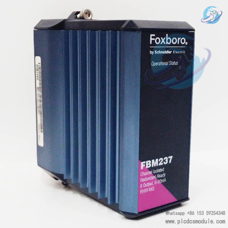
Channel & Signal Characteristics
Redundancy Assurance Mechanism
When a fault is detected in one module, the output of the faulty module will automatically drive down to 0 mA, while the corresponding channel of the normal module will seamlessly take over to provide the correct current output, ensuring uninterrupted field signals. In addition, the redundant power supply of the modules is combined through the diode "OR" logic in the redundancy adapter, further improving power supply reliability. The module also supports configurable options such as fail-safe action configuration (hold/fallback), channel-independent analog output fail-safe fallback data (default set to 0 mA), fieldbus fail-safe enable and delay time setting, minimizing the risk of "fault high level".
Hardware Design & Reliability
The high-reliability design is reflected in multiple aspects: either module in a redundant pair can be hot-swapped and replaced without interrupting field output signals, disconnecting field device wiring, power supply and communication cables. The module microprocessor not only executes analog output application programs but also has built-in safety routines to continuously verify the module health status. Combined with the high coverage rate of fault detection, it significantly improves the uptime of the subsystem. The integrated front-end LED indicators can visually display the module operating status, facilitating maintenance personnel to quickly troubleshoot problems.
Communication & Installation Compatibility
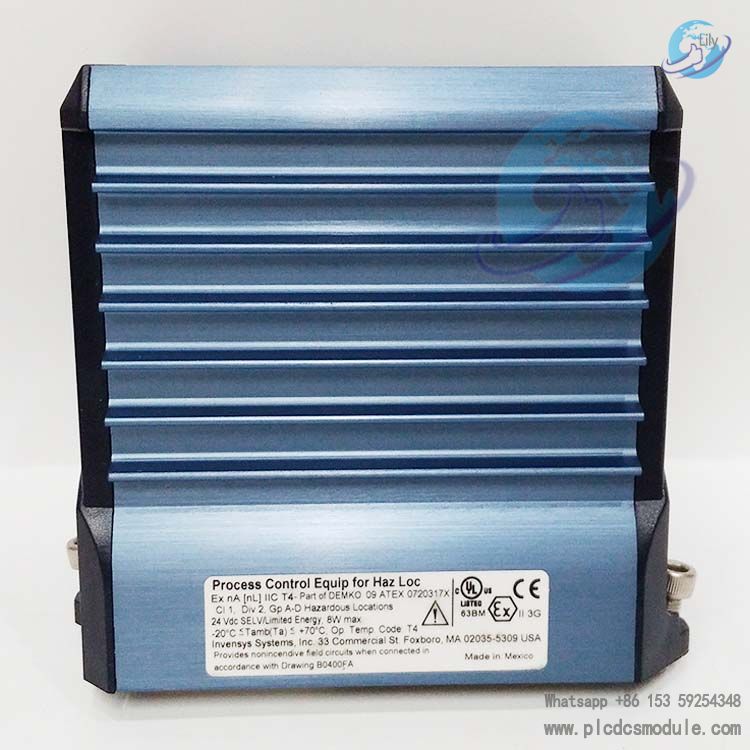
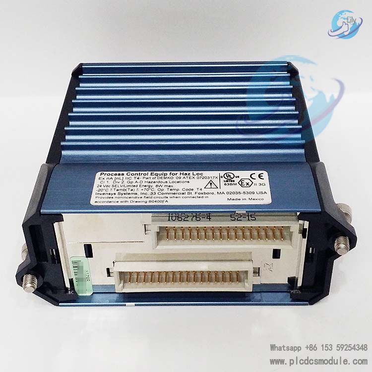
It features flexible installation methods: the module must be mounted on a standard modular backplane, which supports DIN rail mounting (horizontal or vertical) or 19-inch rack mounting (installation kit required). Redundant modules need to occupy adjacent odd/even position pairs on the backplane (1&2, 3&4, 5&6, 7&8) and be used with a redundancy adapter; non-redundant modules can be mounted via a Series 100 conversion mounting structure. The Terminal Assembly (TA) also adopts DIN rail mounting, compatible with various 32 mm and 35 mm rails, supporting crimp or ring terminal wiring methods, and adaptable to 0.2–4 mm² solid/stranded AWG cables (24–12 AWG) or 0.2–2.5 mm² stranded cables with or without plastic ferrules.
Technical Specifications
Power Supply & Power Consumption
Environmental Adaptability
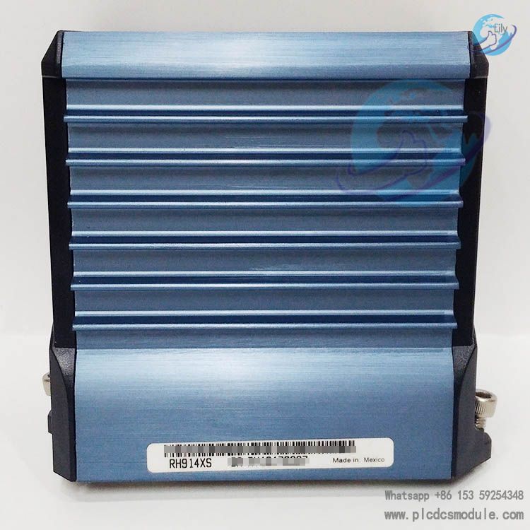
Physical Specifications
Main Functions
I/O Data Processing
The module occupies a single IC66 PLC slot* and asynchronously scans IC66 I/O modules*. It transmits I/O data to the CPU via the backplane of the IC697 PLC rack upon each scan, ensuring real-time data synchronization. Meanwhile, it receives output commands and control instructions (e.g., clearing circuit faults) issued by the CPU and updates them to the corresponding I/O modules.
Communication Node Function
It can serve as a communication node to connect other bus controllers, PCIM modules and IC66 devices* via the IC66 bus*, establishing a communication network between multiple PLCs and upper computers and supporting peer-to-peer data transmission.
Fault Management
Faults reported by the bus controller are centrally managed by the PLC alarm processor. Fault information is recorded with timestamps and stored in tables, facilitating user inquiry and troubleshooting.
3.4 Command Interaction Support
It performs command interaction with the CPU via a communication window, supporting 15 categories of core commands including pulse test output, configuration read/write, diagnostic information read, global output enable/disable, and datagram transmission. These functions satisfy the requirements for system debugging, configuration and operation control.
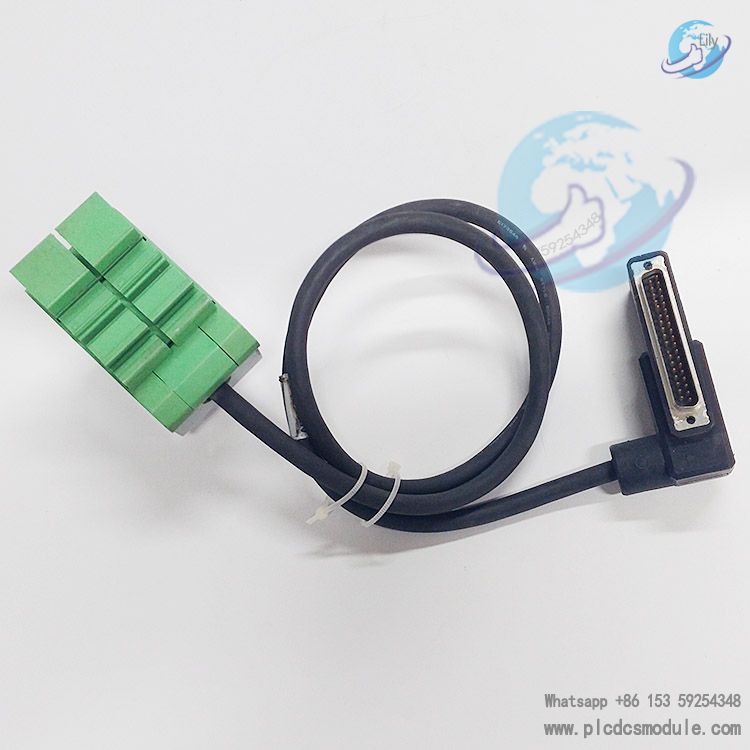
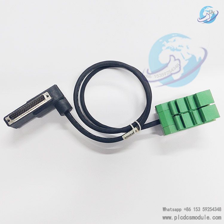
Supporting Components
Key Supporting Components
Redundancy Adapter: Model RH916QD (used for connecting redundant pair modules to the Terminal Assembly).
Terminal Assembly (TA): Available in multiple specifications including crimp type and ring terminal type. Certain models (e.g., RH917QZ) come with built-in bypass jacks and support the connection of I/A Series Output Bypass Stations (P0900HJ), facilitating output maintenance without interruption.
Wiring Cables: Offered in a variety of length specifications. Polyurethane cables (Type 1 P/PVC) have an operating temperature range of -20°C to +80°C, while Low Smoke Zero Halogen (LSZH) cables (Type 1 LSZH) feature an operating temperature range of -40°C to +105°C. Refer to Table 3 for specific model selection corresponding to cable lengths.
Customers who purchased this product are also browsing the following products:
Foxboro P0916PW FBM217 Discrete Input Module
FOXBORO FBM217 P0914TR discrete input module
FOXBORO FBM201 RH914SQ Analog Input module
Foxboro H92A049E0700 DCS module


 3005319639