Note; All products on this site are special products, the market price has been fluctuating, the specific customer service offer shall prevail, because the product is a new product, the picture is not a real shot, please confirm with customer service before placing an order model and product, price and other details, the site used, new are for sale, please contact customer service communication. Honeywell CC-PWRR01 (Model No. 51199939-100) is a core redundant power supply product in the Series C Power System family, specially engineered to provide a stable +24Vdc DC power supply for compatible equipment in industrial automation applications. It is widely used in Experion control systems to power critical components including C300 controllers, IOTAs (Input/Output Terminal Adapters) and IOMs (Input/Output Modules). Boasting redundant design as its core feature, the system eliminates the risk of single-point failure via dual power module configuration. It also features a standardized hardware structure, well-specified electrical parameters and flexible installation adaptability, meeting the stringent industrial environmental requirements for power supply reliability and stability. As such, it serves as one of the key infrastructure components ensuring the continuous operation of control systems.
Download
Core Product Positioning and Hardware Composition
1. Core Positioning
CC-PWRR01 is a standard redundant power supply in the Series C Power System, differentiated from the non-redundant CC-PWRN01 and the CC-PWRB01 equipped with a 24V backup battery. Its core function is to ensure the continuous output of a stable +24Vdc power supply under normal AC input conditions through the redundant design of dual power modules, without battery backup. It is suitable for industrial scenarios where certain power supply continuity is required, and the power failure protection can be supplemented by an external UPS (Uninterruptible Power Supply).
2. Hardware Composition
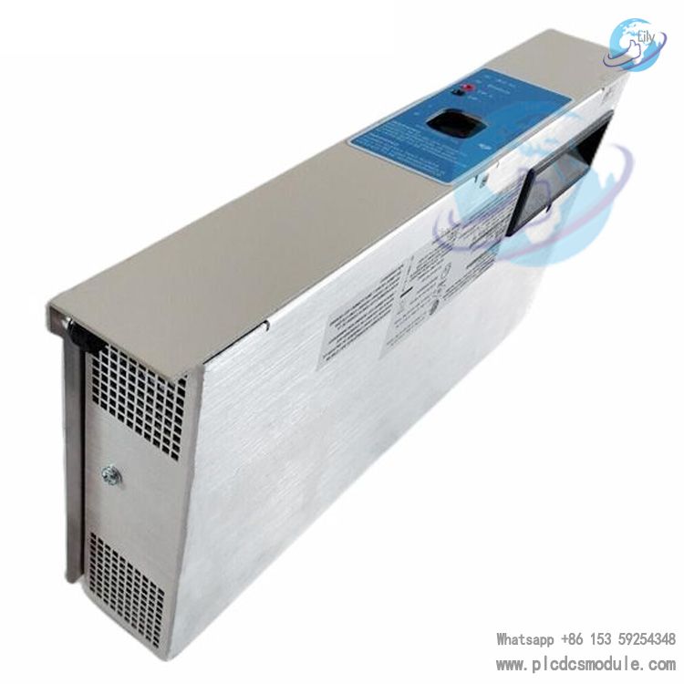
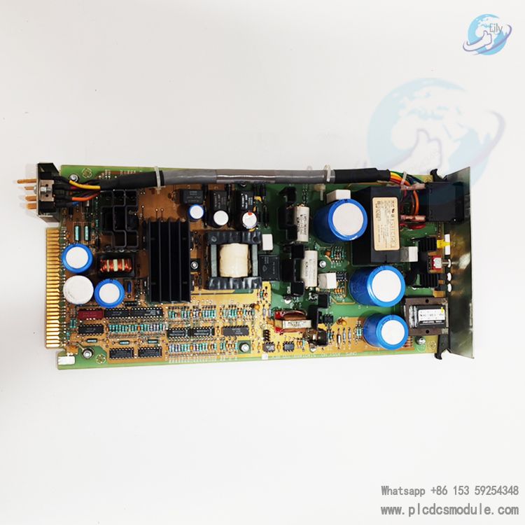
In accordance with the definition of "Series C power system parts" in the documentation, the hardware configuration of CC-PWRR01 includes the following basic components, all integrated into a standardized metal enclosure:
- Dual 20A Power Modules: The system comes standard with two 20A power supplies of model 51199299-100, forming a redundant architecture. Each module can independently output 24Vdc power; if one module malfunctions, the other can seamlessly take over the power supply to avoid power interruption.
- Metal Enclosure: The enclosure serves to fix and protect internal components, and can accommodate a maximum of two power modules (without backup battery components, distinguishing it from CC-PWRB01). Meanwhile, the enclosure is designed to match the installation dimensions of Series C cabinets and can be installed in conjunction with other Series C components (e.g., HDPB Horizontal DC Bus Bars).
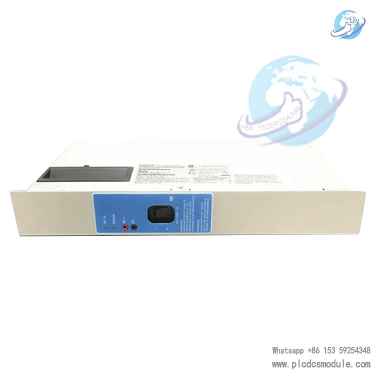
- 8-Port Top Interface Board: Located on the top of the metal enclosure, it includes 6 x 24Vdc power distribution ports (for connecting to the power distribution subsystem and supplying power to CCAs (Card Assemblies) in the cabinet), 1 x C300 controller memory battery backup component port (for connecting to CC-SCMB01/02 memory backup modules), and 1 x power system alarm contact port (for fault alarm signal output and realizing remote monitoring).
Key Electrical Parameters and Operating Characteristics
1. Input and Output Parameters
The electrical parameters of CC-PWRR01 are strictly matched to the power supply requirements of industrial automation scenarios, with the specific specifications as follows:AC Input is 120/240 VAC, supporting a wide range of AC input to adapt to industrial power supply standards in different regions; the two power modules can be separately connected to two independent AC sources (e.g., main power supply and UPS) via external wiring to further improve input redundancy.DC Output Voltage ranges from 25 to 26 Vdc, which is only output when the AC input is normal with a stable voltage range, meeting the power supply voltage requirements of Series C components (e.g., C300 controllers, IOM modules) — all Series C components in the documentation are compatible with 24Vdc power supply with allowable voltage deviation.DC Output Current is 20A; the output current of a single module is 20A, and the total output current can support 20A when the dual modules are connected in parallel for redundancy. The redundant architecture operates in an "N+1" mode instead of current superposition to ensure output stability.Heat Dissipation is 145 Watts; according to the "Series C Hardware Attributes" table, the heat dissipation of CC-PWRR01 is 145W, so heat dissipation and ventilation must be considered in cabinet design to prevent excessive internal temperature from affecting the service life of components.
2. Redundant Operating Mechanism
The redundant design of CC-PWRR01 is based on either "active-standby" or "parallel current sharing" logic (the specific mode is not clearly specified in the documentation, in line with the conventional design of industrial redundant power supplies):During normal operation, the dual power modules run simultaneously to share the load current together, or one module is for active output and the other is in standby mode;When a fault is detected in one module (e.g., abnormal output voltage, overcurrent, overheating), the system can automatically cut off the faulty module, and the normal module independently bears the entire load. The entire switching process has no obvious voltage fluctuation to ensure that downstream equipment (e.g., C300 controllers) is not affected;Faulty modules can be replaced without interrupting the system power supply (hot-swappable design, not explicitly mentioned in the documentation, while Series C components generally support industrial-grade hot-swapping), reducing maintenance downtime.
3. Battery-Free Backup Characteristic
Special attention should be paid to the fact that CC-PWRR01 does not include a 24V backup battery component, distinguishing it from CC-PWRB01. Therefore, when the AC input is completely interrupted (without an external UPS), the system will immediately stop DC output and cannot provide continuous power supply for downstream equipment after a power failure. If power failure protection is required in the scenario, an external UPS must be additionally configured, or the CC-PWRB01 model with a backup battery should be selected.
Comparison of Differences with Other Series C Power Supply Systems
To clarify the positioning of the CC-PWRR01, a comparison of its differences with the other two standard power supply systems (CC-PWRB01 and CC-PWRN01) specified in the documentation is required, with the details as follows:
In terms of the number of power modules, the CC-PWRR01 (51199939-100) is equipped with 2 modules for redundancy, the CC-PWRB01 (51199940-100) also has 2 modules for redundancy, while the CC-PWRN01 (51199937-100) features only 1 non-redundant module. For backup battery components, the CC-PWRR01 comes with no such components, the CC-PWRB01 is fitted with a backup battery assembly including a rechargeable battery and a charger that can maintain a 24-25Vdc output for 30 minutes after a power failure, and the CC-PWRN01 has no backup battery components either.
In terms of DC output voltage under normal AC input conditions, all three models deliver a voltage of 25-26 Vdc. When a power failure occurs, the CC-PWRR01 and CC-PWRN01 have no DC output, whereas the CC-PWRB01 can maintain a 24-25Vdc output for 30 minutes. For heat dissipation, the CC-PWRR01 and CC-PWRB01 both have a heat dissipation of 145W, while the CC-PWRN01 has a lower heat dissipation of 125W.
In terms of applicable scenarios, the CC-PWRR01 is suitable for scenarios that require redundant power supply and allow for external UPS connection; the CC-PWRB01 is intended for scenarios that demand both redundant power supply and short-term protection after a power failure (such as data preservation); the CC-PWRN01 is applicable to cost-sensitive scenarios with low requirements for power supply continuity.
Installation and Compatibility Requirements
1. Cabinet Installation Compatibility
Installation Location: Must be installed in a standard Series C cabinet. The enclosure dimensions are compatible with the internal card slots of the cabinet, allowing for co-layout with components such as the power distribution subsystem (e.g., HDPB Horizontal DC Bus Bar) and C300 controllers.AC Input Wiring: For maximum redundancy, it is recommended to connect the two power modules to two independent AC sources (e.g., main power supply and UPS) respectively. Wiring must comply with the grounding requirements specified in the document Series C Hardware Grounding Considerations to ensure safe AC grounding (the grounding wire is green and connected to the cabinet's AC safety grounding bar).
2. Connection to the Power Distribution Subsystem
The CC-PWRR01 must supply power to the in-cabinet CCAs (Card Assemblies) via the Power Distribution Subsystem (Part Number: 51199406-100), with the specific connection path as follows:24Vdc power distribution port of the CC-PWRR01 (one of the six ports on the top 8-port interface board) → 9-inch DC power cable (51202324-100);DC power cable → HDPB Horizontal DC Bus Bar (51403896-100, including mounting hardware);HDPB → red/black wire pair (51202335-300) → in-cabinet CCAs (e.g., C300 controller IOTAs, IOM modules).
For power supply to dual-access cabinets (with CCAs on both the front and rear sides), additional red/black wire pairs are required. It is also necessary to verify that the output current of the CC-PWRR01 can meet the total power consumption of the CCAs on both sides. If the current is insufficient, an additional set of power supply system and power distribution subsystem must be configured.
Application Scenarios and Selection Recommendations
1. Application Scenarios
Based on the redundant characteristics and battery-free backup design of the CC-PWRR01, its applicable scenarios mainly include the following:
- Experion control systems with moderate reliability requirements: Such as non-critical process control loops in the chemical and petrochemical industries. Power failure protection can be supplemented by an external UPS, and the dual power modules prevent single-point failures at the same time.
- Scenarios with pre-deployed UPS: If a UPS is already configured on-site (to provide power failure protection for the entire cabinet), the dual power modules of the CC-PWRR01 can work in conjunction with the UPS to form a dual protection of "UPS + power supply redundancy", reducing the risk of single-point failures of the UPS.
- Multi-cabinet collaborative power supply scenarios: Through the HDPB bus bar of the power distribution subsystem, the CC-PWRR01 can supply power to CCAs on one or both sides of the cabinet. When matched with other Series C power supply systems, it enables unified power management of multiple cabinets.
2. Selection Considerations
- Power failure protection requirements: If the scenario requires short-term power supply after a power failure (e.g., for saving memory data of C300 controllers), the CC-PWRB01 with a backup battery shall be selected instead of the CC-PWRR01.
- Load current calculation: It is necessary to confirm whether the 20A output current of the CC-PWRR01 can meet the demand based on the total current consumption of all Series C components in the cabinet (refer to the current value of each component in the Series C Hardware Attributes table in the documentation). If the total current exceeds 20A, the number of power supply systems must be increased.
- Grounding compliance: During installation, it is imperative to strictly follow the requirements of the document Series C Hardware Grounding Considerations and connect the AC safety ground and cabinet frame ground to a compliant grounding system (e.g., AC safety ground rod, supplementary ground rod) to avoid power interference or safety risks caused by poor grounding.
Related Spare Parts and Compatible Components
To ensure the maintenance and expansion of the CC-PWRR01, the documentation specifies its compatible spare parts and collaborative components, as detailed below:
- Replacement power modules: When a single power module malfunctions, the 20A power module of model 51199299-100 is replaceable for it.
- Power distribution components: It must be matched with the 51199406-100 power distribution subsystem, 51202324-100 DC power cable and 51403896-100 HDPB bus bar to realize power distribution.
- Memory backup components: If memory backup is required for C300 controllers, the CC-SCMB01 (for 1-2 C300s) or CC-SCMB02 (for more than 2 C300s) memory backup modules can be connected via the top interface, and powered by matching the 51202331-100 power cable (55 inches).
- Alarm expansion components: External alarm devices (e.g., audible and visual alarms, PLC input modules) can be connected through the alarm contact interface to realize local or remote fault alarm.
Customers who purchased this product are also browsing the following products:
HONEYWELL 05701-A-0301 Single Channel Control Card
Honeywell 05701-A-0326 FIELD INTERFACE CARD
Honeywell CC-PDOB01 51405043-175 24Volt Digital Output module
Honeywell LCNP4E 51405098-100 Interface Card


 3005319639