


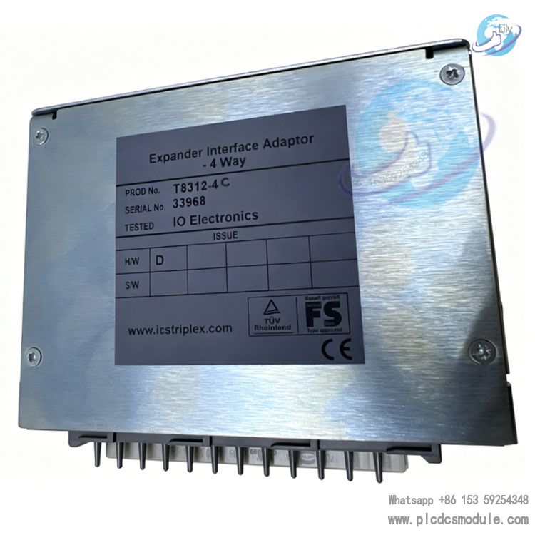
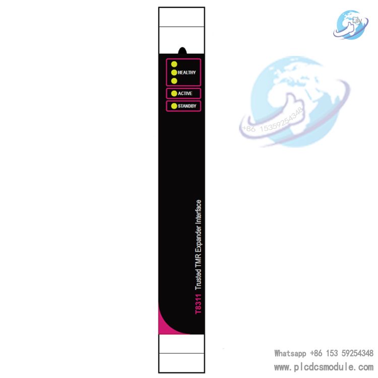
The ICS Triplex T8312-4C is a high-integrity expansion interface adapter within the Trusted MR (Triple Modular Redundancy) control system. It is specially designed to connect the controller chassis with multiple expansion chassis, supporting flexible expansion of distributed control architectures. This 4-channel model enables seamless interconnection and data exchange between the controller and up to 4 expansion units. Featuring a fully shielded design and locking connectors, it ensures reliable signal transmission in harsh industrial environments.
Core Functions and Features
TMR Redundant Architecture: Adopting Triple Modular Redundancy technology, each input channel is equipped with three independent signal paths. Single-channel faults will not affect system operation, greatly improving the reliability of safety-critical systems.
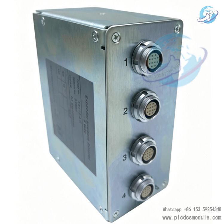
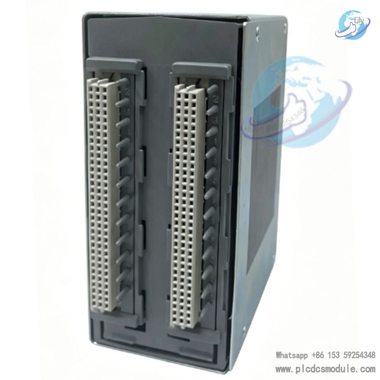
4-Channel Expansion Capability: Equipped with four 12-pin ODU connectors for connecting expansion chassis and one 96-way Type C connector for interfacing with the expansion interface module of the controller chassis. A single module can connect up to 4 expansion chassis.
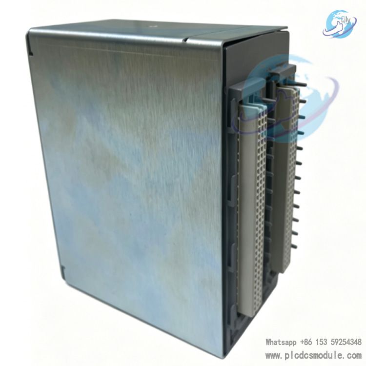
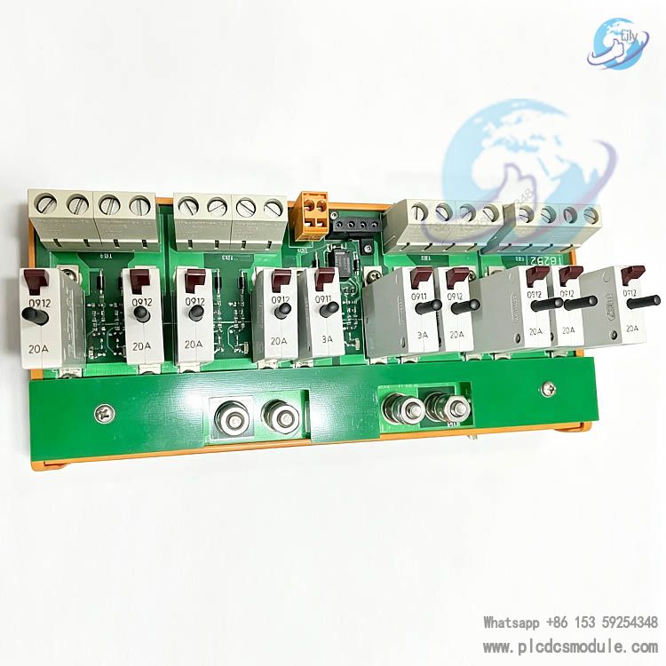
Full EMC Shielded Design: With a metal enclosure and fully shielded PCB layout, it effectively resists electromagnetic interference (EMI/RFI) and complies with industrial electromagnetic compatibility standards.
Locking Connectors: Interfaces adopt connectors with locking mechanisms to prevent loose connections caused by vibration or external force, enhancing long-term operational stability.
Integrated Diagnostics and Hot Standby: It supports comprehensive fault diagnosis, monitoring and testing for fast fault location. Featuring hot standby capability, it allows on-site maintenance and hot-swap module replacement.
Wide Temperature and Environmental Adaptability: Operating temperature range
Technical Specifications
Model | T8312-4C (4-channel expansion)Compatible System | ICS Triplex Trusted™ TMR Control SystemConnectors | 4 × 12-pin ODU (expansion chassis side); 1 × 96-way Type C (controller side)Expansion Capacity | Up to 4 expansion chassisCommunication Protocol | Modbus TCP/IP, Modbus RTU supportedOperating Temperature | -40°C ~ +70°CStorage Temperature | -40°C ~ +85°CRelative Humidity | 5% ~ 95% (non-condensing)Dimensions | 133mm×133mm×63mmWeight | Approx. 0.65kgIngress Protection | IP20 (finger touch protection)
Mechanical & Installation
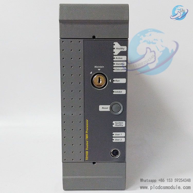
Mounting Method: Features a snap-fit design for direct attachment to the rear connectors of the controller chassis. It can be removed by pressing the release button without additional tools required.
Chassis ID Configuration: Chassis ID is set via DIP switches. The controller chassis is fixed as ID 1, while expansion chassis are sequentially configured as ID 2, 3, 4 and 5.
Housing Material: Metal enclosure, providing both electromagnetic shielding and mechanical protection.
Application Scenarios
Primarily applied in safety-critical industrial sectors including oil & gas, power generation, chemical and pharmaceutical industries. It expands the I/O capacity of the Trusted TMR control system to meet the demands of large-scale distributed control.
FAQ
What is the difference between T8312-4C and T8312-7C?
The T8312-4C is a 4-channel expansion model, connecting up to 4 expansion chassis. The T8312-7C is a 7-channel version, supporting a maximum of 7 expansion chassis. Both models share identical hardware interfaces and functions, with only the channel quantity differing.
Is hot swapping supported?
It supports hot standby and on-line replacement. The module can be plugged and unplugged during system operation without affecting the overall control logic, provided official maintenance procedures are strictly followed.
How to configure the expansion chassis ID?
Set the ID via the DIP switches on the expansion chassis. The controller chassis ID is fixed as 1, and expansion chassis IDs must be uniquely configured in the sequence of 2, 3, 4 and 5 to avoid address conflicts.
How to troubleshoot communication faults?
First, check whether the connectors are fully locked and cables are in good condition. Second, check interface status and fault codes through system diagnostic tools. Finally, verify correct chassis ID configuration and network protocol settings.
Is an independent power supply required?
No separate power supply is needed. The module draws operating power from the rear connector of the controller chassis, simplifying wiring and installation.


 3005319639