


This module interconnects multiple chassis systems using Unshielded Twisted Pair (UTP) cables while fully preserving the fault tolerance and high-bandwidth characteristics of the IMB bus. Leveraging Hardware-implemented Fault Tolerance (HIFT) TMR architecture, it provides fault containment for the Expander Bus, the module itself, and the controller chassis IMB, localizing fault impact and maximizing system availability. It also enables rapid fault identification through comprehensive diagnostics and monitoring mechanisms, supporting hot-standby and module spare slot configurations. As a critical fault-tolerant device for bus expansion in industrial Safety Instrumented Functions (SIF), it is TÜV-certified and complies with IEC 61508 SIL 3 safety requirements.
Download
| Parameter | Specification |
|---|---|
| Backplane (IMB) Power Supply | 20 Vdc ~ 32 Vdc |
| Field Power Supply | None (N/A) |
| Power Consumption | 54 W (backplane-powered) |
| Mounting Location | T8100 I/O module slot |
| Insulation Category | 50 V basic insulation (between module and backplane power) |
| Fuse | Non-user-serviceable |
| Maximum Expansion Communication Distance | TC-301 copper cable: 30 m; T8314 fiber-optic transceiver unit: 10 km |
| Operating Temperature | 0°C ~ +60°C (32°F ~ 140°F) |
| Storage Temperature | -25°C ~ +70°C (-13°F ~ 150°F) |
| Operating/Storage Relative Humidity | 10% ~ 95%, non-condensing |
| Dimensions (H × W × D) | 266 mm (10.5 in) × 31 mm (1.2 in) × 303 mm (12.0 in) |
| Weight | 1.14 kg (2.5 lb) |
Core Architecture and Design Features
TMR Triple Modular Redundancy Architecture
The module operates in a 3-2-0 fault-tolerant mode with three primary Fault Containment Regions (FCR A, B, C) and one non-critical monitoring and display region (FCR D). Each primary FCR independently integrates an Expander Bus interface, an IMB bus interface, master/standby interfaces with other T8311C modules in the chassis, control logic, communication transceivers, and power supply units. FCR D is responsible for monitoring, display, and cross-FCR Byzantine voting.Physical isolation between FCRs prevents fault propagation at the hardware level, ensuring that a single-region fault does not disrupt overall system operation.
Hardware-Implemented Fault Tolerance (HIFT)
Dedicated hardware and software testing mechanisms enable extremely fast fault detection and response, supporting automatic fault handling without spurious alarms. All bus communications and control signals are triple-redundant and processed via Byzantine majority voting, automatically correcting message errors, masking single-channel faults, detecting and reporting signal discrepancies to avoid potential latent failures.
Independent Power Distribution
The module receives dual redundant +24 Vdc power from the Trusted controller chassis backplane. Each internal FCR derives its own independent power, further enhancing power-level fault tolerance and preventing complete module failure due to a single power fault.
Main Functions
Bus Message Forwarding
As the core of IMB bus expansion, the active T8311C module receives messages from the controller chassis IMB bus, resynchronizes and validates them via Byzantine majority voting, then forwards them to the triple-redundant Expander Bus. It also receives response messages from the Expander Bus, performs identical voting and verification, and transmits them back to the IMB bus, enabling reliable data exchange between the controller chassis and expansion chassis. All message transactions support error correction to ensure communication integrity.
Control Signal Forwarding
The module continuously monitors and forwards three categories of fully triple-redundant control signals:
- Power fault warnings
- System watchdog signals
- Command response signals
Signal paths follow:TMR Processor → T8311C Module → Expansion Processor → I/O ModuleSignals are synchronized and voted at both the module and expansion processor ends, maintaining synchronization in the expansion chassis even if faults occur in the controller chassis.
Status Monitoring and Data Acquisition
The module records and reports real-time critical operating data to the TMR processor, including:
- Expander Bus link quality (receive error counters, link status)
- Receive message errors by link/FCR (frame errors, checksum errors, data mismatches)
- HIFT clock master/slave status and switch records
- FCR watchdog status
- Current module active/standby status
- IMB bus status
- Module model, serial number, and physical insertion/removal status
This provides comprehensive data support for system diagnostics.
Intelligent Active/Standby Switching
Supports hot-standby configuration. By default, the module powers up in Standby mode and only responds to commands addressed to itself over the IMB bus. In Active mode, it performs full bus message and control signal forwarding.Active/standby switching is controlled by the TMR processor via command messages. Built-in interlocking ensures that a pair of active/standby modules never enter active mode simultaneously. When both modules are healthy, the left module defaults to active; automatic switchover to the healthy module occurs upon fault detection.
Installation and Configuration Requirements
Physical Installation
The module must be installed in I/O slots of the T8100 controller chassis. It must not be installed in the triple-width main chassis processor slots (to avoid module damage).For dual-module redundancy:
- Configure adjacent slots in the system configuration tool
- Left slot must be odd-numbered
- Even-numbered slots only serve as backups for the corresponding odd-numbered slots
- Dual slots are interconnected via the T8312 Expansion Interface Adapter Unit
- The module connects to expansion processor modules via TC-301 Hot Link cables
- Remote expansion chassis use T8314 fiber-optic transceivers and TC-302 cables
Module Insertion and Replacement
The module contains electrostatic-sensitive devices. All handling must comply with ESD protection procedures. Do not touch exposed connector pins or remove the module housing.Inspect the module and connector pins before installation. Damaged or bent-pin modules must be replaced directly; manual correction is not permitted.Hot replacement is supported:
- Unlock the original module using the ejector tool
- Wait for the system to complete active/standby switchover
- Remove the faulty module only after it enters standby mode
Do not remove an active module directly—this will force modules in the chassis into a default shutdown state.
Cable Polarization/Keying
The module is factory-keyed to prevent incorrect installation. Field cables must have keying pins 1, 2, and 6 removed to match the module keying. For dual-slot configurations, both cables must be polarized.
System Configuration
No additional module-specific configuration is required. However:
- Chassis and slot numbers must be entered in the Trusted system I/O Connection Table
- OEM parameters: Chassis ID fixed at 1, slots 1–8 (odd-numbered for primary modules)
- The System.INI file must define both primary and hot-standby positions to enable hot-swapping
- Chassis assignment is configured once and automatically synchronized to the standby position
Communication Bus Parameters
Expander Bus
- Triple-redundant point-to-point architecture
- Independent command and response media for each channel
- Communication via Unshielded Twisted Pair (UTP)
- Data rate: 1.5 Gbps
- Cable fault tolerance: single-channel cable fault allows expansion processor to continue full triple-redundant operation
Inter-Module Bus (IMB)
- Triple-redundant design
- Maximum data rate: 12.5 Mbps
- Handles:
- 8-bit bidirectional data bus
- Bus clock / module enable control signals
- System watchdog signals
- Power fault warning signals
- Slot position signals
- 4-bit chassis ID encoding
All signals are triple-redundant for reliable inter-module communication within the controller chassis.
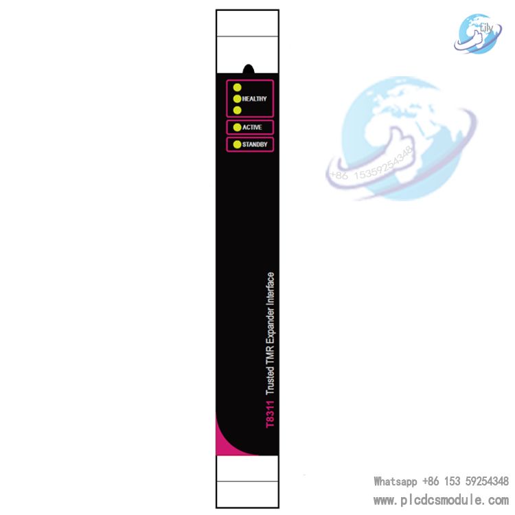
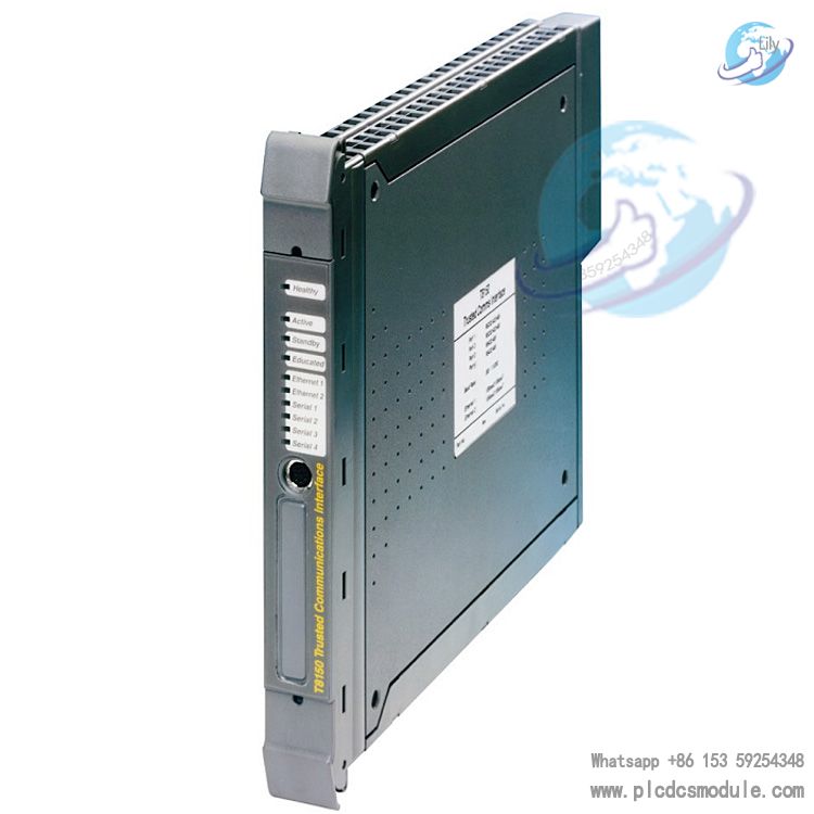
Front Panel and Status Indicators
The front panel features health, active, and standby LEDs to provide intuitive operating status feedback for field maintenance:
- Health LEDs: 3 LEDs correspond to channels A, B, C.
- Solid green: channel healthy, no faults
- Flashing red: fault detected in the corresponding channel
- Active LED: Solid green = module in Active mode, performing bus message and control signal forwarding
- Standby LED: Solid green = module in Standby mode, responding only to its own commands, not participating in bus forwarding
Troubleshooting and Maintenance
Core Troubleshooting Logic
The module provides a clear fault-symptom–cause–solution mapping. Common faults include:
- All panel LEDs off: power fault – check chassis power supply
- Single FCR LED flashing red: single-region fault – module continues operation; replacement recommended
- Multiple FCR LEDs flashing red: fault exceeds fault tolerance – remove inactive module immediately; replace active module only after system switchover to standby
- Standby LED flashing: software-detected fault, system switched to standby module – remove faulty module
BIU error counters can be viewed via diagnostic tools:
- Incrementing counter on one module: interface module fault
- Incrementing counters across the entire chassis: expansion processor fault
Maintenance Requirements
- All maintenance must be performed by qualified personnel with electronic equipment experience and safety system training
- In flammable or explosive hazardous areas, do not insert or remove modules under power
- Confirm safe atmosphere before performing work
- Avoid portable communication devices near the module to prevent RF interference; warning labels recommended
- Module PCB is non-removable
- Connectors:
- 185-pin DIN 41642 type (SK1, IMB bus)
- 96-pin DIN 41612 Type C (PL4, Expander Bus)
No user-serviceable fuse components
Customers who purchased this product are also browsing the following products:
T8310/T8310C: Trusted TMR Expansion Processor Module
T8312: Expander Interface Adapter Unit
T8314/T8314C: Fibre Tx/Rx Unit for Remote Expander Chassis
T8300/T8300C: Core Backplane Module for Expander Chassis
T8110B: Trusted TMR Core Processor Module
9100: High-reliability TMR Redundant Controller Module
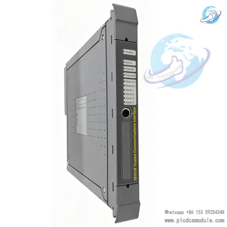
T8151B: Trusted TMR Communication Interface Module
T8403/T8403C: 24V DC Digital Input Module
T8431/T8431C: 24V DC Analog Input Module
T8451: 24V DC Digital Output Module
T8461/T8461C: 24/48V DC Digital Output Module
T8480/T8480C: Analog Output Module
T8231: 24V DC 750W Universal Input Power Module
T8830: Expander Interface Module
T8850: 40-channel Analog/Digital Output Terminal Module
T8873: 16-channel Isolated Digital Output Terminal Module
TC-301: Expander Interface Hot Link Cable
TC-302: Fibre Tx/Rx Unit Connection Cable


 3005319639