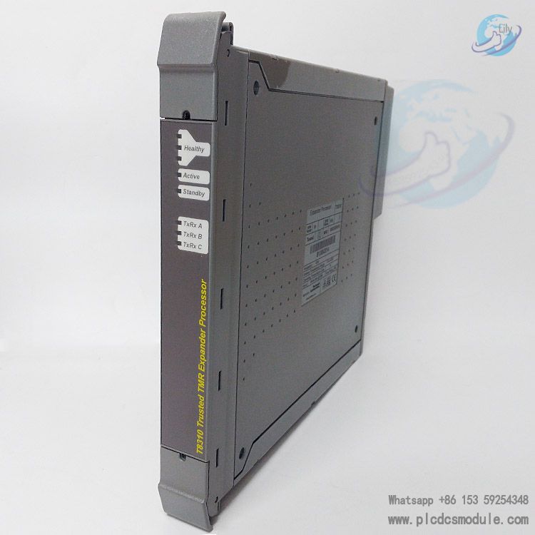
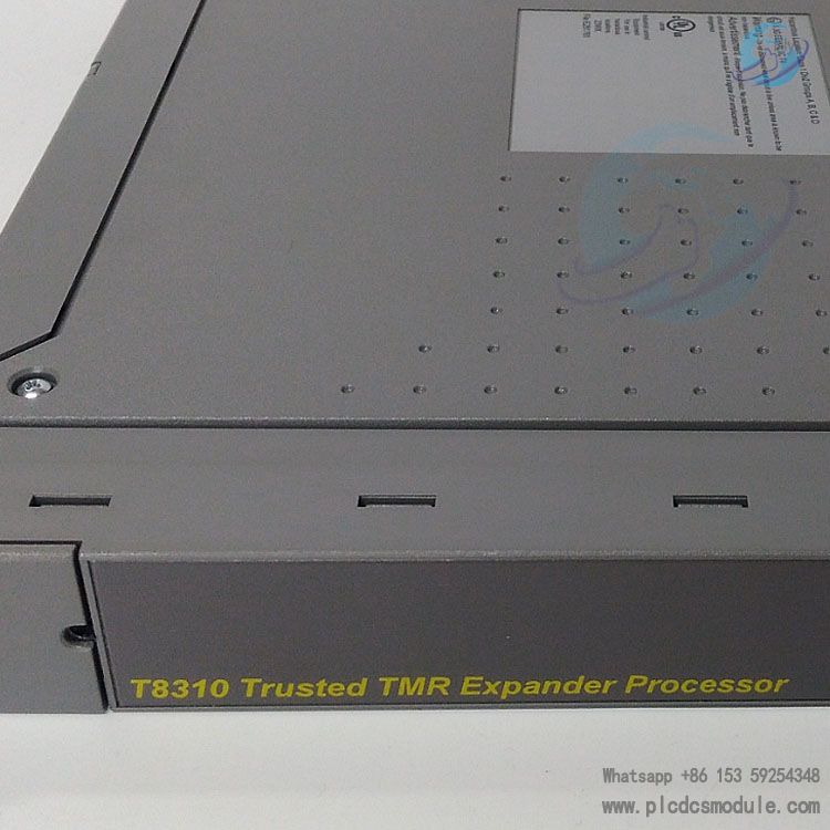
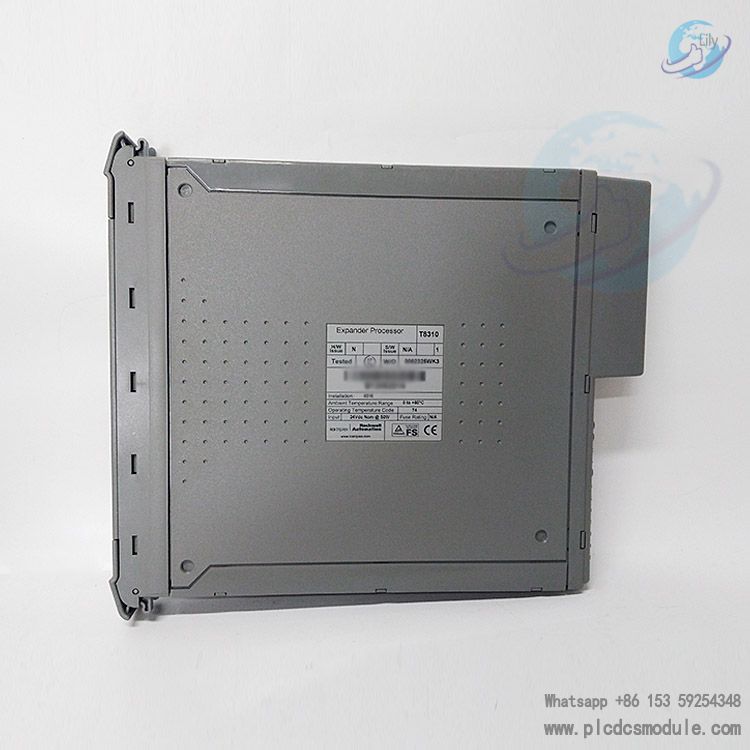
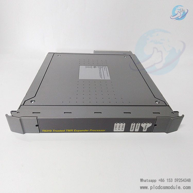
Note; All products on this site are special products, the market price has been fluctuating, the specific customer service offer shall prevail, because the product is a new product, the picture is not a real shot, please confirm with customer service before placing an order model and product, price and other details, the site used, new are for sale, please contact customer service communication. The ICS TRIPLEX T8310 Trusted TMR Expander Processor is a module installed in the processor slot of the Trusted expansion chassis, providing a "slave" interface between the expansion bus and the backplane of the expansion chassis. The expansion bus allows connecting multiple chassis systems using unshielded twisted-pair (UTP) cables while maintaining the fault-tolerant and high-bandwidth inter-module bus (IMB) capability. This module adopts a hardware-implemented Triple Modular Redundancy (HIFT TMR) architecture with fault isolation function, which can limit the impact of potential faults to a local area, maximize system availability, and support hot standby and module redundancy configurations. It enables rapid fault identification through comprehensive diagnosis, monitoring, and testing.
DATA SHEET
 ICS TRIPLEX T8310.pdf
Structure and Working Principle
Architectural Design: Based on the TMR architecture and adopting a lockstep configuration, it includes three main fault containment regions (FCR A, B, C). Each region is equipped with interfaces for the expansion bus and IMB, main/standby interfaces with other TMR expander processors in the chassis, control logic, communication transceivers, and power supplies. The fourth fault containment region (FCR D) provides non-critical monitoring and display functions and is also part of the Byzantine voting structure between FCRs. Isolation is provided between each FCR where interfaces are needed to prevent fault propagation.
Communication Mechanism: Communication with the TMR processor is realized through the TMR expansion interface module and the triple modular expansion bus. The expansion bus is a triple modular point-to-point architecture, with each channel containing independent command and response media. Voting at the expansion bus interface can tolerate cable faults. Communication with I/O modules in the expansion chassis is realized through the IMB on the chassis backplane, and all transactions are voted to ensure that faults are confined to the IMB.
Installation-related
- Installation Location: It must be installed in the two leftmost processor slots (PL1 and PL2) of the expansion chassis and cannot be installed in other module positions, otherwise, the module may be damaged. The two processor slots need to be interconnected with a cable cover assembly, and the expander processor module is connected to other modules through specific cables.
- Module Insertion/Removal and Replacement: The module contains electrostatically sensitive components, so electrostatic handling regulations must be observed. Do not touch exposed connector pins or disassemble the module housing. Before installation, check whether the module is damaged and whether the type is correct, and record relevant information. If it is a new chassis or the first configuration, the chassis address must be set correctly first. When replacing the module, insert the new module into the vacant processor slot, and the switch can be started through the ejector tab or the diagnostic interface command.
- Cable Connection and Replacement: The replacement of the expansion bus cable assembly must be carried out after the system is shut down. When removing and inserting cables, specific steps must be followed to ensure correct alignment and fixation.
Message Forwarding: It can forward messages received from the expansion bus to the expansion chassis IMB, forward response messages received from the expansion chassis IMB to the expansion bus, and perform resynchronization and majority voting (Byzantine voting) on the received messages.
Control Signal Forwarding: The active TMR expansion interface module continuously monitors and transmits signals such as power failure warnings, system watchdogs, and command response controls. These signals are fully triple modular and are forwarded to the expansion chassis IMB by the TMR expander processor module.
Other Functions: It generates three independent IMB power supplies to power the triple modular IMB interfaces of the interface modules in the expansion chassis; provides synchronized IMB clock signals; monitors the 24V power supply and generates status information; records various information such as expansion bus link quality and message errors and provides them to the TMR processor.
Standby Mode: After the internal power level is stable, the module enters this mode by default. It can receive messages addressed to itself, but only sends response messages through the expansion bus after switching to the active mode, and cannot transfer messages between other modules in the expansion chassis.
Active Mode: Responsible for forwarding messages from the expansion bus to the expansion chassis IMB and forwarding response messages from the expansion chassis IMB to the expansion bus, while having all the functions of the standby mode.
Master-Slave Control: The two TMR expander processor modules negotiate to control the switching of master-slave modes to ensure that they will not be in active mode at the same time in the master/slave configuration. When both modules are normal, the active mode is by default in the leftmost module.
Fault Reporting: Faults are reported to users through the LED indicators on the front panel of the module and status variables, mainly including external wiring faults and module faults, which require on-site correction of wiring and module replacement respectively.
Common Problems and Solutions: For example, if all front panel indicators are off, it may be due to lack of power or FCR D failure. It can be judged by checking the status of other modules and communication conditions and taking corresponding measures; if the indicator of a single or multiple FCRs flashes red, it may be a fault of the corresponding FCR, and the replacement time should be determined according to whether the module is active or not.
Power Supply: The backplane of the Trusted expansion chassis provides dual redundant +24V DC power supply. Each FCR independently obtains the required power supply. The backplane (IMB) power supply range is 20-32Vdc, and the power consumption is 45W.
Communication Distance: When using TC-301 copper cable, the maximum expansion communication distance is 30m; when using T8314 optical fiber transceiver unit, it can reach 10km.
Environmental Parameters: Operating temperature is 0-60°C, storage temperature is -25-70°C, and relative humidity during operation and storage is 10%-95% (no condensation).
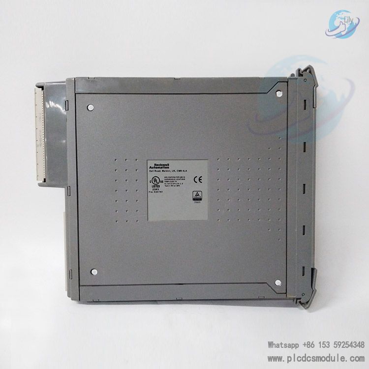
Physical Dimensions: Height 266mm, width 31mm, depth 303mm, weight 1.33kg.
Customers who purchased this product are also browsing the following products:
ICS TRIPLEX T8110B Trusted TMR Processor Module
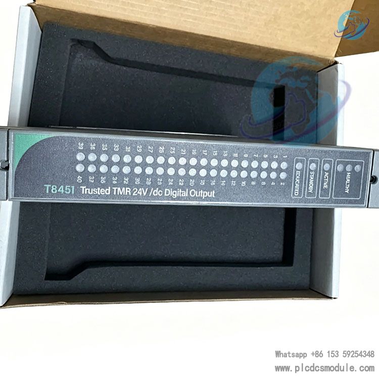
ICS TRIPLEX T8461 Trusted TMR 24 Vdc Digital Output Module
woodward 8200-1302 505D STEAM TURBINE CONTROL
ABB PFCA401SF 3BSE024387R4 Control unit


 3005319639